Maitry07
Advanced Member level 4
Hello support team,
I have tried to implement the Xilinx FFT IP core as below.
I samples data format: FIX16_15
Q samples data format: FIX16_15
FFT window:1024
Sample rate: 20.48 MSPS
Output: unscaled
Output number of bits: 0 to 63 ( out of which 58 to 32 bits represent XK_IM and 26 to 0 bits represent XK_Re)
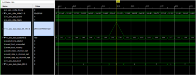
I have attached the screenshot of the same.
Now as per xilinx user guide, The index(xk_index: m_axis_data_user ) should be taken into account at which we are getting the highest peak amplitude of FFT output.
In the screenshot,
My input frequency is 3 MHz,
Highest peak index: 150
Frequency estimation = (Sample rate* index)/FFT window = (20.48 *10^6 *150)/1024 = 3 MHz
So, in this way I am getting the correct result. right now, I have verified it through the ILA.
But my actual requirement is to figure out the index value from the peak amplitude and take it further this index value to estimate the frequency. and then there is one fix frequency value (let's say 32 MHz ) needs to be added to the estimated 3 MHz frequency. so could you please suggest what kind of algorithm i can use to search for the correct index out of the total 1024 window?
I have tried to implement the Xilinx FFT IP core as below.
I samples data format: FIX16_15
Q samples data format: FIX16_15
FFT window:1024
Sample rate: 20.48 MSPS
Output: unscaled
Output number of bits: 0 to 63 ( out of which 58 to 32 bits represent XK_IM and 26 to 0 bits represent XK_Re)
I have attached the screenshot of the same.
Now as per xilinx user guide, The index(xk_index: m_axis_data_user ) should be taken into account at which we are getting the highest peak amplitude of FFT output.
In the screenshot,
My input frequency is 3 MHz,
Highest peak index: 150
Frequency estimation = (Sample rate* index)/FFT window = (20.48 *10^6 *150)/1024 = 3 MHz
So, in this way I am getting the correct result. right now, I have verified it through the ILA.
But my actual requirement is to figure out the index value from the peak amplitude and take it further this index value to estimate the frequency. and then there is one fix frequency value (let's say 32 MHz ) needs to be added to the estimated 3 MHz frequency. so could you please suggest what kind of algorithm i can use to search for the correct index out of the total 1024 window?