cyber_dev
Junior Member level 1
Hi all,
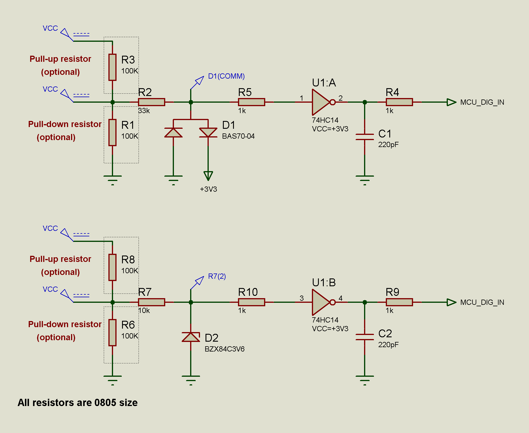
I am designing a digital input circuit. It should accept the input state as logic high from 4V to 40V. I will also use the same circuit to measure the frequency of input signal (PWM). The frequency to be measured is up to 25kHz. The input will have a pull down or pull up resistor optionally. I need your suggestions regarding the circuits shown below.
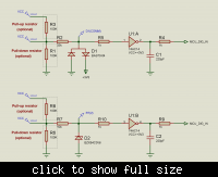
For the first circuit with schotky diodes,
datasheet of diode
1-) What is the path for reverse leakage current of the diodes? The datasheet says that Ir = 100 nA max. @25°C and it is about 30 uA @125°C. Assume that there is a 100K pull down resistor at input. If no external signal is applied to input, what would be voltage at input for the worst case? Would the reverse current generate a voltage across the pull down resistor? If so how much?
2-) Replace the resistor (33K) (which is in series with diodes) with a resistor that have value of 1M. What would change? (The question is the same as above.)
For the second circuit with zener diode,
1-) The zener diode capacitance is given 450 pF @25°C in the datasheet. With a low impedance (<1K) source, can a 25 kHz signal's frequency be measured correctly even if @125°C temperature?
In general, which circuit above do you suggest me to use? Is there a need for modification? Thanks in advance.
Best Regards.
I am designing a digital input circuit. It should accept the input state as logic high from 4V to 40V. I will also use the same circuit to measure the frequency of input signal (PWM). The frequency to be measured is up to 25kHz. The input will have a pull down or pull up resistor optionally. I need your suggestions regarding the circuits shown below.
For the first circuit with schotky diodes,
datasheet of diode
1-) What is the path for reverse leakage current of the diodes? The datasheet says that Ir = 100 nA max. @25°C and it is about 30 uA @125°C. Assume that there is a 100K pull down resistor at input. If no external signal is applied to input, what would be voltage at input for the worst case? Would the reverse current generate a voltage across the pull down resistor? If so how much?
2-) Replace the resistor (33K) (which is in series with diodes) with a resistor that have value of 1M. What would change? (The question is the same as above.)
For the second circuit with zener diode,
1-) The zener diode capacitance is given 450 pF @25°C in the datasheet. With a low impedance (<1K) source, can a 25 kHz signal's frequency be measured correctly even if @125°C temperature?
In general, which circuit above do you suggest me to use? Is there a need for modification? Thanks in advance.
Best Regards.
