viperpaki007
Full Member level 5

- Joined
- Jul 2, 2008
- Messages
- 274
- Helped
- 11
- Reputation
- 22
- Reaction score
- 8
- Trophy points
- 1,298
- Location
- Finland
- Activity points
- 3,437
Follow along with the video below to see how to install our site as a web app on your home screen.
Note: This feature may not be available in some browsers.


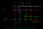
Try something like the schematic shown in the image. Here I am taking 5uA reference current, converting it into a 1uA current and then generating the references for the 1uA current. You can change according to your need.
The different colours mark the different bias lines.
As long as the input bias current is constant, the bias voltages would correspond to it ie it would track across process and temperature.
Also the sizes should match with what you have in your circuit for the best matching.
For the size of the cascode bias generators namely mpb21/mpb22 and mn10/mn13, the size of the bottom device(mpb21/mn10) should be about 1/3 of the size of the top device(mpb22/mn13). You can derive this since the bottom devices are in triode.
View attachment 99423

Can you explain the benefits of cascode bias generators for DC bias generation? I know self cascode transistor has longer equivalent L and larger output impedance. How to relate this characteristic to DC bias generation? Also, can you provide more details on why the bottom device size should be about 1/3 of top device size?


Hi niyishn5,
Can you explain the circuit a bit more. If the bottom transistors are acting as current mirrors then why they have to be in triode region and why there sizes should be 3 times smaller.