neazoi
Advanced Member level 6

- Joined
- Jan 5, 2008
- Messages
- 4,157
- Helped
- 13
- Reputation
- 26
- Reaction score
- 15
- Trophy points
- 1,318
- Location
- Greece
- Activity points
- 37,198
Hello, I experiment with the possibility of using a miniature reed relay (PRMA1A05) as a source for high frequency generator (purely electromechanical).
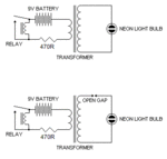
I have seen the next schematics in a website. The schematics are as in the website, the only addition I made was the addition of the resistor, to avoid sort circuit of the coil, when driving low impedance transformers, like toroids with low number of windings.
First I tried the first circuit. The transformer I used was a 1:1 toroid (because I did not need high voltage) taken out of a switched mode PSU. Instead of the neon bulb, I connected a 1Mohm digital storage scope. The fastest frequency I could get (self resonance of relay coil and transformer coils) was about 150KHz and that was the average frequency because the relay does not oscillate in constant frequency. Of course the relay cannot oscillate too much but I do not know how my scope frequency counter does the counting (resonances etc).
In the second circuit the author states that the spark gap increases the frequency. I have not yet tried it, but I was thinking to use a step-up transformer and a spark-gap like shown to generate high voltage. Then I could resonate this gap to a higher frequency using an LC. Maybe this will stabilize the frequency as well. I could use a HV transformer instead of a relay to generate the HV, the only reason I used the multivibrator scheme was to increase the output frequency (reed relays can oscilalte much faster than 50Hz). But if usung a spark-gap (https://en.wikipedia.org/wiki/Spark-gap_transmitter) an ordinary 50Hz HV transformer could be used?
Could I do something like this, would this work? The basic diagram of a spark-gap transmitter shows how this could work https://upload.wikimedia.org/wikipedia/commons/e/e6/Spark_gap_transmitter_diagram.png
Or any other proposed scheme?
My intention is to somehow generate a frequency signal (low power) on HF using electromechanical or transformer devices.
Attachments
Last edited:


