Continue to Site

Welcome to EDAboard.com

Welcome to our site! EDAboard.com is an international Electronics Discussion Forum focused on EDA software, circuits, schematics, books, theory, papers, asic, pld, 8051, DSP, Network, RF, Analog Design, PCB, Service Manuals... and a whole lot more! To participate you need to register. Registration is free. Click here to register now.

Reduction of Ripple current in Buck input electrolytic caps?

cupoftea

Advanced Member level 5
Joined
Jun 13, 2021
Messages
2,611
Helped
54
Reputation
108
Reaction score
115
Trophy points
63
Activity points
13,687
Hi,
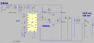
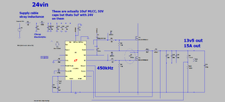
We are doing a Buck as attached (LTspice and PNG) of 24-32Vin, 13v5 out, 15A out and 450kHz.

As can be seen, Our input filter comprises five 10uF,50V,1210 MLCC's and two 220uF, 63V, Alu Electrolytics. (Nichicon UUJ1J221MNJ6MS)

The two 220uF caps at the input are just there for some damping of the input.
As such, there is a total of 6.4A (ACrms) of ripple current at the Buck input.
We want as little of that as possible to be drawn from the 220uF caps, since they
only have 350mA of ripple current rating.

As such, we will place 1Ohm, 2512 resistors in series with them.
Why is it we see our competitors not bothering to do this?
 

Attachments

  • Cap ripple current.png
    Cap ripple current.png
    56.7 KB · Views: 38
  • Buck_capRippleCurr.zip
    2.2 KB · Views: 28
Hi,

these 220uF capacitors are for low frequency!! (mains frequency) and are no low_ESR ones.
I´d say they are pretty useless in a 450kHz application.

If my mind calculation is correct then the 5x 10F result in Xc of 7mOhms.
The voltage ripple is about 400mV pp. (with or without the 200uF capacitors)

If you consider realistic ESR and ESL for these unsuitable 220uF capacitors I expect to get negligible capacitor current and negligible power dissipation (Which determines the allowed ripple current).

****
You use a simulation tool. So use it correctly and meaningful:
It should be easy to measure the voltage ripple with this tool. (much faster and more precise than my mind calculations)
It should be easy to put in realistic ESR and ESL values ... and then measure the capacitor currents.

Klaus
 
We want as little of that as possible to be drawn from the 220uF caps, since they
only have 350mA of ripple current rating.

As such, we will place 1Ohm, 2512 resistors in series with them.
Why is it we see our competitors not bothering to do this?
So where is that high current going to come from if not the capacitors?
 
Above about 70kHz the electro's are all inductive - so they don't add anything to the HF ripple current capability -

excepting the rare case - which some times occurs - where the ESL of the electro's forms a nice parallel resonance with the remaining MLCC's nearby at the same freq as the switching ripple - then you can get a goodly number of amps in all the caps !
 
Above about 70kHz the electro's are all inductive - so they don't add anything to the HF ripple current capability -
Thanks, yes i agree, and we will actually thus change to the attached, whereby there is just one lone electro right at the input connector, and it is there , only, to cancel out supply cable inductance ringing with the input. It is upstream of the filter inductor, so will see no ripple current...(not that it would anyway being dirt cheap , inductive electro).
Its a pretty lone, ineffective 47u, dirt cheap electro, but remove it and the whole thing rings like mad.

And the only reason we use so many 1210, 10uf, 50v MLCC's is that we want the LC ringing frequency of the input filter to be well below the switching frequency.
 

Attachments

  • Buck input_modified.png
    Buck input_modified.png
    58.4 KB · Views: 25
  • Buck_capRippleCurr_modified.zip
    2.2 KB · Views: 21
Hi,
Its a pretty lone, ineffective 47u, dirt cheap electro, but remove it and the whole thing rings like mad.
I personally don´t think it´s a good idea to use the "erroneous operation" of a device to build a reliably working circuit.

These "errors" you use as feature are not specified, thus they may change with: Age, temperature, production batch, production plant...

Especially production batch:
The manufacturer may improve the device´s performance from time to time.. and since it´s an improvement they do not need to report the improvement.
So you buy the exact same article .. it works now (for your application), but not necessarily in a year.
So you now design a part in that maybe later does not fulfill "your personally desired (mal)function" anymore.

If not very well documented (by you) it calls for trouble. No information for buying the "correct" device over years, or for second sources or repair...

****
It´s like buying especially dirty, low quality steel to make (lossy, low quality) springs for a car to avoid using true dampers. It´s exactly what you do just translated to mechanical parts.
(I avoid writing here what I really think about this idea)

Klaus
 
Thanks, but its perfectly reliable...the 47uF cap at the input connector (in post #6) does not work with "erroneous operation"....it sucessfully damps out any ringing with the supply cable inductance. The 47uF electro cap passes virtually none of the switching ripple.......because its upstream of the filter inductor.

When i said it was "ineffective", i was being a little harsh to it, sorry about that...i meant that it plays no part in filtering the switching frequency ripple....but i was being too unkind to the cap...it does a great job of damping out any supply cable stray inductive ringing.

I wasnt sure what any objection was to the 47uF cap in the post #6 above? It does a fine job, and is just the most dirt cheap 47uF electro cap you can find at 63V.
 
Last edited:
By installing a series inductor preceding a filter capacitor, I find it causes a switching converter to draw smooth current from a power source (in simulation).

As for its Henry value that can be about the same as the inductor (or transformer) used in the converter. The capacitor shall be large enough so its charge stays high.
 
Thanks, but its perfectly reliable
I just took your informations.

if you have a ringing caused by L and C... and you add a C then it just shifts down rsosnance frequency. But it causes no damping.
Damping is caused by "dissipating power". This is not what an L or a C does. Both just "store" energy.
An R dissipates power and thus causes damping. (so not the real C, but the erroneouns R)

Your explanation of using this (dirt cheap) capacitor .. to suppress ringing makes sense. It works. But not due to it´s capacitance but because of it´s ESR.

****
But back to your concern of post#1:
There you were concerned about the capacitor ripple current of 6A caused by the switching frequency.
So this problem does not exist.

Klaus
 
Above about 70kHz the electro's are all inductive - so they don't add anything to the HF ripple current capability -
Thanks, yes, we would like to derive the ESR and series L of an electrolytic capacitor so that we can discern exactly how much of the ripple current will flow in it. (concerning the schem in the top post, and the fitting of the electro cap just downstream of the input filter inductor)
The problem is that the electro cap datasheets dont give info to allow the series L to be calculated.
Also, they give tan delta = ESR/Xc, but in fact, the ESR varies with frequency, so we wouldnt know what it was at the switching frequency.
As such, do you agree, that without the help of a frequency analyser to examine the electro cap with, we cannot calculate the strays of this electro cap?
.....and it is because of this, that we are compelled to "not" have any electro caps downstream of the input filter inductor. Would you agree this is our best bet? (unless of course the electro cap is rated to carry the full ripple current, but in our case, it is not)

Eg, the EDK476M063 electo cap
...its datasheet does not allow us to calculate the stray series L.....but we need to know this as part of calculating how much of the ripple current will flow in the capacitor when it is placed just downstream of the input filter inductor.
 
Last edited:
A simple resonance test of the electro's - or using a VNA on the finished pcb will tell you if you have any series or closed LC ckts that are resonant at the sw freq.
 
A simple resonance test of the electro's - or using a VNA on the finished pcb will tell you if you have any series or closed LC ckts that are resonant at the sw freq.
True.

Still one has to take
* aging
* change of capactiance due to temperature
* change of capactiance due to applied DC voltage
into account.

So it´s not a critical single resonant frequency, but a whole critical frequency band.

Klaus
 

LaTeX Commands Quick-Menu:

Similar threads

Part and Inventory Search

Welcome to EDABoard.com

Sponsor

Back
Top