roineust
Member level 3

- Joined
- Jul 2, 2013
- Messages
- 58
- Helped
- 0
- Reputation
- 0
- Reaction score
- 0
- Trophy points
- 1,286
- Activity points
- 1,903
Hello there!
Here is my problem:
I have this micro servo:
**broken link removed**
There is a 5V power supply and separately from that power supply, an Arduino that sends 5V signals to the servo.
I managed to lower the power supply to 4.06V, by using 2 1N400x diodes, one after the other.
When finished to successfully lowering the power supply voltage, i got to the task of also lowering the Arduino signal from 5V to ~4V, i first tried to go without lowering the voltage - the servos did respond to signals, but where also moving and jerking, when no signal was sent - so i concluded that this is because the voltage is too high.
Now i was focusing on how to lower the signal to ~4V and i understood, that using a diode will not be good, since it will not enable the servo to feedback to the Arduino (?) as well, will cut the lower half of the signal sine wave (?) or something of the sort....
So i went to an Arduino forum and got an advice to build something that is called a voltage divider.
I was referred to a schematic of the voltage divider circuit here:
**broken link removed**
And was told, that i need a certain ratio between the resistors, and was given the choice of, either R1 = 2k2 and R2 = 10k Or R1 = 1k and R2 = 4k7 , i chose the 1k and 4k7 option.
What happened next, was that the servos totally stopped responding.
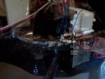
Please take a look at the attached picture of the circuit i soldered.
Can you please help me understand what seems to be the problem?
Thanks a lot!
Attachments
Last edited:

