Continue to Site

Welcome to EDAboard.com

Welcome to our site! EDAboard.com is an international Electronics Discussion Forum focused on EDA software, circuits, schematics, books, theory, papers, asic, pld, 8051, DSP, Network, RF, Analog Design, PCB, Service Manuals... and a whole lot more! To participate you need to register. Registration is free. Click here to register now.

Reducing noise in buck converter powering push pull inverter

Bruno5234

Newbie level 5
Joined
Feb 28, 2024
Messages
10
Helped
0
Reputation
0
Reaction score
0
Trophy points
1
Activity points
113
Hi, I designed a buck converter that powers a push pull inverter that I designed too, I want to control the voltage in the buck converter while powering the inverter, the problem I'm facing is that I can control de voltage in the buck converter pretty easy when putting a resistor load, but when I connect the inverter as a load (with a resistor load at the secondary of the inverter's transformer) I can see some high frequency noise at the output of the buck converter and I want to reduced it because I don't want to damage my microcontroller and I'm also getting a bad voltage reading because of this noise, I tried increasing the size of the bulk capacitor of the buck converter and that decreased the amplitude of the noise but made my control system slower, so I think that is not the way to solve the problem. Any ideas?
This is the schematic of my circuit:
Buck converter:
1709089894705.png

And this is the PCB I designed:
1709089952401.png

Push Pull Inverter circuit:
1709089982639.png

Push Pull Inverter PCB
1709090000246.png


I don't know a lot about PCB design so I probably made a mistake with the design
The Buck converter is control by a PWM of 32 kHz frequency, the push pull inverter is working with 200 kHz of frequency
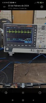
The noise I'm getting is this:
WhatsApp Image 2024-02-27 at 9.20.21 PM (1).jpeg

The frequency of the noise is the double the frequency of the inverter, so I think the problem has to be the inverter
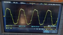
I don't know if this provide some extra information but this is the waveform I get at the secondary of the inverter
WhatsApp Image 2024-02-27 at 9.20.21 PM.jpeg

The transformer I'm using for the inverter is a toroidal transformer designed for the frequency of the inverter

Please let me know if you need extra information

Thank you for answering :)
 

Attachments

  • WhatsApp Image 2024-02-27 at 9.20.21 PM (1).jpeg
    WhatsApp Image 2024-02-27 at 9.20.21 PM (1).jpeg
    95.6 KB · Views: 34
  • WhatsApp Image 2024-02-27 at 9.20.21 PM.jpeg
    WhatsApp Image 2024-02-27 at 9.20.21 PM.jpeg
    71.4 KB · Views: 42
1709416091359.png
In order to reduce deadtime in this design
insert Schottky diode in series gate resistor for fast shutoff and parallel 15 to 45 ohms, try 25 Ohms

1709416424870.png

--- Updated ---

You can also display Ch1- Ch2 and try to measure DC current in centre tap.
 
If you are really trying to get the push pull going at 200kHz ( 4.8uS each way + dead time ) - then you will be exciting all the resonances in the unknown transformer.

Without a tightly coupled transformer and VERY short wires to local decoupling - there will be spikes on the Vds of each fet at turn off - that will make it back into the supply bus - in this case the buck converter.

If the Vout of the transformer is at higher voltages - then the capacitance of the windings becomes very important - there will be a main parallel resonance and other resonances ( load dependent ) that will be kicked into action by the fast edges of the driving mosfets - which is why resonant techniques are mainly used to do what you appear to be trying to do.

I will have a more detailed read of the above and see what needs commenting further.
--- Updated ---

The IR2104 cannot give you low enough dead time - per the data sheet:
1709422672429.png

You need to organise your gate drive such that 200nS dead time ( adjustable ) is obtainable

With just the right amount of dead time you can get a nice resonant transition ( assuming other caveats I posted are followed ) so that when the Vds of the device turning off reaches 2 x Vin the other device is turning on - this leads me to another point -

your turn off gate drive is not aggressive enough - ideally the gate should fall from 10 to zero in 30nS for lossless turn off - here however the slower turn off you have in your ckt at least reduces the Vds overshoot - due to all the wiring inductance !

There is no successful 200kHz operation without the tightest possible layout, i.e wiring L to an absolute minimum - de-coupling as close as possible with quality film and electrolytics ( again with shortest possible leads - ideally all on a multi-layer pcb ) Fet's back to back, etc

p.s. we design power supplies in the 1kW - 4kW bracket that have an operating range of 200kHz - 400kHz
--- Updated ---

Just one further thing - if the capacitance of the output wdg is 120pF say and the inductance of the output winding is say 5.27mH

then the parallel resonance of this combination is . . . . - - - > 200 kHz

if you are unlucky enough to be near this combination - then there will be some high currents flowing in the mosfets, there will also be a sinusoidal output perforce the action of the parallel resonance - the current in the ( nominal )120pF wdg capacitance will be ( @ 565V rms ) 85mA = 48 VA reactive.

p.p.s the freq of the ringing you have observed above, Vds, is a product of the mosfet Cds, and the leakage / wiring inductance of the circuit, as you take away the wiring and leakage inductance ( between LV wdgs - these should be bifilar and intertwined ) then the freq will go up - and the amount of snubbing required to reduce the peaks will reduce - in a very well laid out ckt - no snubbers are required ( we don't need any ).

Good luck.
 
Last edited:
View attachment 189100In order to reduce deadtime in this design
insert Schottky diode in series gate resistor for fast shutoff and parallel 15 to 45 ohms, try 25 Ohms
I'll check if I have Schottky diodes, if not, I'll buy some on Monday. Is a SR100 good enough? Any recommendation? I can easily get SR3100, SR5100 and 1N5819
View attachment 189101
--- Updated ---

You can also display Ch1- Ch2 and try to measure DC current in centre tap.
I'm confused, how exactly should the connection be?
Like this?
1709425865564.png

How many ohms should the series resistor have?

If you are really trying to get the push pull going at 200kHz ( 4.8uS each way + dead time ) - then you will be exciting all the resonances in the unknown transformer.

Without a tightly coupled transformer and VERY short wires to local decoupling - there will be spikes on the Vds of each fet at turn off - that will make it back into the supply bus - in this case the buck converter.

If the Vout of the transformer is at higher voltages - then the capacitance of the windings becomes very important - there will be a main parallel resonance and other resonances ( load dependent ) that will be kicked into action by the fast edges of the driving mosfets - which is why resonant techniques are mainly used to do what you appear to be trying to do.

I will have a more detailed read of the above and see what need commenting further.
--- Updated ---

The IR2104 cannot give you low enough dead time - per the data sheet:
View attachment 189102
You need to organise your gate drive such that 200nS dead time ( adjustable ) is obtainable

With just the right amount of dead time you can get a nice resonant transition ( assuming other caveats I posted are followed ) so that when the Vds of the device turning off reaches 2 x Vin the other device is turning on - this leads me to another point -

your turn off gate drive is not aggressive enough - ideally the gate should fall from 10 to zero in 30nS for lossless turn off - here however the slower turn off you have in your ckt at least reduces the Vds overshoot - due to all the wiring inductance !

There is no successful 200kHz operation without the tightest possible layout, i.e wiring L to an absolute minimum - de-coupling as close as possible with quality film and electrolytics ( again with shortest possible leads - ideally all on a multi-layer pcb ) Fet's back to back, etc

p.s. we design power supplies in the 1kW - 4kW bracket that have an operating range of 200kHz - 400kHz
--- Updated ---

Just one further thing - if the capacitance of the output wdg is 120pF say and the inductance of the output winding is say 5.27mH

then the parallel resonance of this combination is . . . . - - - > 200 kHz

if you are unlucky enough to be near this combination - then there will be some high currents flowing in the mosfets, there will also be a sinusoidal output perforce the action of the parallel resonance - the current in the ( nominal )120pF wdg capacitance will be ( @ 565V rms ) 85mA = 48 VA reactive.

p.p.s the freq of the ringing you have observed above, Vds, is a product of the mosfet Cds, and the leakage / wiring inductance of the circuit, as you take away the wiring and leakage inductance ( between LV wdgs - these should be bifilar and intertwined ) then the freq will go up - and the amount of snubbing required to reduce the peaks will reduce - in a very well laid out ckt - no snubbers are required ( we don't need any ).

Good luck.
Okay, I'm gonna reduce the wires in the transformer, about the driver, I don't know enough driver models, I was thinking in replacing it with a IR2110 or a IR2184 because they can provide a lot more current, but looking at the datasheet the dead time is almost the same, any recommendation?
--- Updated ---

You can also display Ch1- Ch2 and try to measure DC current in centre tap.
The signal in the center is CH1-CH2
WhatsApp Image 2024-03-01 at 4.58.08 PM.jpeg
 
As shown will increase deadtime . WShich is OK . You need to correlate Ciss specs with R*Ciss and gate to drain prop delays to learn this.

The asymmetric delays are already build into your driver but too much for 5 Ohms on this higher RdsOn FET. Rg rises with Rdson which reduces Ciss and Coss due to size.

You may experiment with the R*Ciss delays to get the deadtime reduced. Try change 5 to 25 only , measure before and after delays then compute a correction to speed up the riseing for alling edges to change the deadtime as you like. But parasitics stored energy will respond to a change in switch state. Use A-B or Ch 1-2 as a 3rd channel.
--- Updated ---

How much AC ripple do you have at the centre tap?
Your Caps ought to be within 1 cm of the load.
 
Last edited:
the dead time for this ckt and 200kHz could well be in the region of 50 - 80nS - looking the the wave-forms given so far,

really this needs a zero dead time drive and the use of Rgate * Ciss to give the turn on dead time, with aggressive pnp assisted turn off to give a very fast turn off.
 
the dead time for this ckt and 200kHz could well be in the region of 50 - 80nS - looking the the wave-forms given so far,

really this needs a zero dead time drive and the use of Rgate * Ciss to give the turn on dead time, with aggressive pnp assisted turn off to give a very fast turn off.
50~80 ns / 2500 = 2 to 3.2% is your estimate and (350~500 ns)/2500ns = 14~25% was my estimate shown (asymmetric delays). The litz wire delay I estimate as 6~7ns/cm / N strands.

1709489548287.png

1709490062979.png

I think the deadtime impedance can be more accurately measured by displaying the centre tap or supply return current at a suitable point and comparing that with Ch1-Ch2 drive voltage, then computing the ratio. This requires a short probe ground loop from star gnd. adding ~ 6.5 ns /cm. delay with ringing.


A 1st order approximation of rise times will be the inductance of primary tap and Rdson of FET.

Tau = L/R @ 63% of step
R= Rdson + wire
Rdson = Vol/Iol
with Tr+ = 35 max and Tr-=25 ns max. on IR2110

2SK3561: RdsOn = 850 mohm max @ 25'C

If Tau were 1us, use RdsOn, L=T/R = 1us / 0.85 = 1.2 uH

Thus reducing the turns will speed up risetimes but increase magnetization current.
 
Last edited:
When the fet turns off - how long does it take for the Vds to rise to 2x Vin ? - this is all the delay you need for the other fet to turn on, and so on.

" Litz wire delay " is an interesting term, I am familiar with 80% of C for coax, but Litz in a small section would seem to introduce no delay to current rise or fall times - indeed any such " Litz delay " would be swamped by leakage inductance AND Cds and Cwdg - which also set Vds rise times at turn off . . .
All 1st order delays are either Tau=L/R or Tau= R*C
Wire inductance L is reduced by N insulated strands hence I call it Litz wire delay which is lower per unit length, which might be negligible if short from Vcc.
2nd order delays are sqrt {L*C} from driver Coss and interwinding C.
Coax delay line or LC all pass filter is the same delay time for any sqrt{L/C}=Zo

I would imagine leakage inductance for magnetization coupling is at least 10x rated min load impedance.
 
Last edited:
As shown will increase deadtime . WShich is OK . You need to correlate Ciss specs with R*Ciss and gate to drain prop delays to learn this.

The asymmetric delays are already build into your driver but too much for 5 Ohms on this higher RdsOn FET. Rg rises with Rdson which reduces Ciss and Coss due to size.

You may experiment with the R*Ciss delays to get the deadtime reduced. Try change 5 to 25 only , measure before and after delays then compute a correction to speed up the riseing for alling edges to change the deadtime as you like. But parasitics stored energy will respond to a change in switch state. Use A-B or Ch 1-2 as a 3rd channel.
--- Updated ---

How much AC ripple do you have at the centre tap?
Your Caps ought to be within 1 cm of the load.
Could you pls give me a diagram? I don't understand how I should to connect the diodes
 
Could you pls give me a diagram? I don't understand how I should to connect the diodes
You schema in #23 shows how to make Turn On delay more than turn off delay where the reference is with respect to Ciss and Rg.

But fundamentally, you need to define all your I/O specs before specific solutions are possible.
Start with a boost inverter with Vdc min:max and Vout min:max and Iout

Are you expecting a sine? If so, you need more than a 2 level switch.
Are you expecting a square wave? then what dI/dt primary and secondary?

I suspect your FET is too high an RdsOn and inductance too undefined for Lp, Lsec and SRF.
I suggest you look at using an 18 mOhm FET rather than 0.8 Ohm one but more important, define your design expectations.

What about the IRFP4668PbF it has RdsOn of 8 mOhm? I would like for the FET to have at least 100V VDS breakdown voltaje
I expect a square wave at the output, I know it doesn't currently look like a square wave but that waveform works for me
 
What about the IRFP4668PbF it has RdsOn of 8 mOhm? I would like for the FET to have at least 100V VDS breakdown voltaje
I expect a square wave at the output, I know it doesn't currently look like a square wave but that waveform works for me
until you define all the specs, I cannot advise.
 

LaTeX Commands Quick-Menu:

Similar threads

Part and Inventory Search

Welcome to EDABoard.com

Sponsor

Back
Top