Continue to Site

Welcome to EDAboard.com

Welcome to our site! EDAboard.com is an international Electronics Discussion Forum focused on EDA software, circuits, schematics, books, theory, papers, asic, pld, 8051, DSP, Network, RF, Analog Design, PCB, Service Manuals... and a whole lot more! To participate you need to register. Registration is free. Click here to register now.

Rechargeable 30 LED burns up on AC

Status
Not open for further replies.
It looks like there was originally a regulator and protection but the manufacturer removed it and linked across it to cut costs.
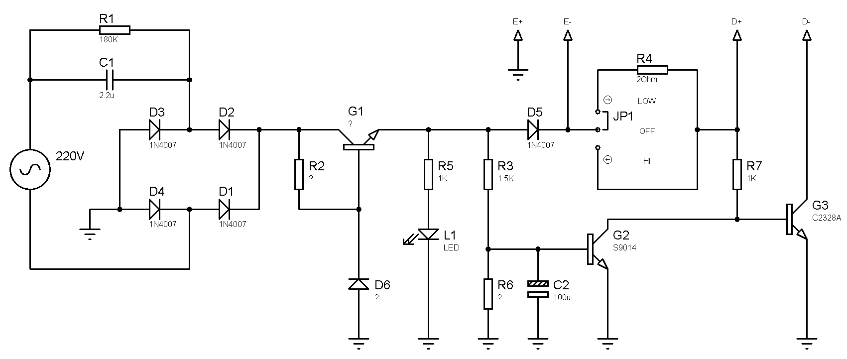
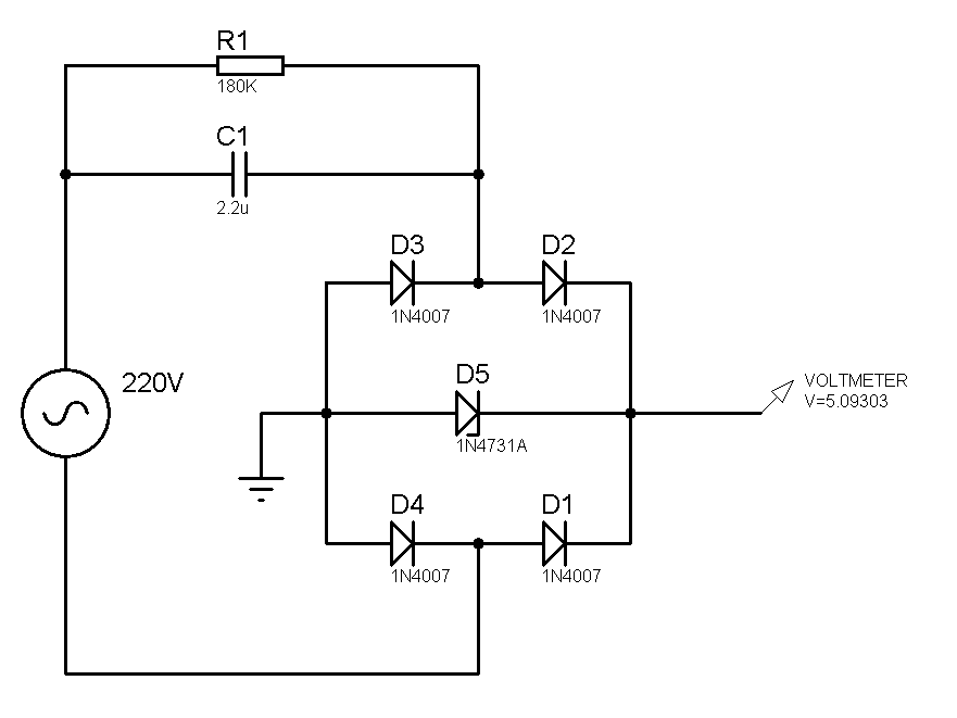
The regulator can't work with a constant current capacitor supply, power dissipation would be too high.
 

Thanks for the schematic.
I redraw it with ISIS :


But if you connect D+ to battery, the base of G3 will use the battery all the time, no?
Is this device designed for 220v?
What is that missing transistor for? Prevent battery overcharging?

So far :
The 180K resistor is for R1 (not R2)
G2 was the wrong way around.
The red wire is used for battery -
The black wire is used for battery +
 

The PCB tracks suggest G1 position is intended to be an NPN transistor (ECB pin out) with D6 being a Zener diode to regulate the voltage but as FvM points out, it would not work properly and that's why I guess the manufacturer linked it out. The other possibility is the board is dual pupose and could be used with a transformer to drop the AC instead of C1, in that case it could make sense to add the components.

I assumed the switch was high or low charge rate to the battery but maybe it is to set the LED array brightness. Either way, the E+ and E- points seem reversed and C2 seems backwards.

Bear in mind the design brief for this was probably like this:
1. lowest possible cost
2. efficiency not important
3. ignore safety issues.
4. warranty expires as soon as it leaves the factory

Brian.
 

There are a lot of typo, but it is clear that the switch is for the LED brightness :


You would think that if a Chinese manufacturer wants to sell its "fantern" in the west they would have its English label made by somebody who can speeky zee Engrish.

A new Chinese grocery store opened in my city. They were selling "Lamp" instead of Lamb because a "p" and a "b" look the same to a Chinese person. The owner of the store drives VERY expensive cars.
Some ceramic tiles high on the front of the store fell down one week after the store opened and nearly killed shoppers. Guess the nationality of the contractor who built the store.
 

Happens everywhere Audioguru. I got directions in Turkey to visit an office under the government mouse. Either it's a very small office or they have serious rodent problem there.

Brian.
 

Might be due to shorted capacitor (the red polyester) since this serve as current limiter on this circuit configuration. i have been experience it once only at open circuit manifestation.

Best regards,
 

It seems the main problem is with the voltage which is too much high, around 190v.
When I add a 4.3v diode zener to D6 the voltage becomes 4v, but after a few tests the diode zener dies.
How can I protect the diode zener?


Your 1N4731A zener diode is rated for 4.3V when its current is only 58mA. Its maximum allowed current is about 200mA when it is at its maximum allowed temperature and it might be at 5V.
Your zener diode dies because its current is too high which cooks it or it is too small for such a high temperature.
 
  • Like
Reactions: 5arid

    5arid

    Points: 2
    Helpful Answer Positive Rating
Besides power dissipation issues, a zener diode regulator is rather inaccurate and can't be adjusted.

It's difficult to save the idea of the simple transformerless circuit if charging control is required, but not completely impossible. My favourite shunt regulator would be a TL431 or LM385 + power transistor combination. A discrete BJT circuit with temperature compensation can do, too.
 
  • Like
Reactions: 5arid

    5arid

    Points: 2
    Helpful Answer Positive Rating
Should be OK.

The important factor is the power dissipation. Calculate that by multiplying the Zener voltage by the current flowing through it. (W = Vz * I). In your circuit I would allow for about 0.2A current although it should be a little lower than that.

You probably want to use a diode with a slightly higher knee voltage, it will still protect the circuit and is less likely to divert charging current from the battery. I suggest 5.6V or 6.8V. It should certainly be > 0.7V more than the voltage across the fully charged battery terminals. The higher voltage will result in a lower current so the power rating isn't compromised by much.

Brian.
 
  • Like
Reactions: 5arid

    5arid

    Points: 2
    Helpful Answer Positive Rating
Status
Not open for further replies.

Similar threads

Part and Inventory Search

Welcome to EDABoard.com

Sponsor

Back
Top