Continue to Site

Welcome to EDAboard.com

Welcome to our site! EDAboard.com is an international Electronics Discussion Forum focused on EDA software, circuits, schematics, books, theory, papers, asic, pld, 8051, DSP, Network, RF, Analog Design, PCB, Service Manuals... and a whole lot more! To participate you need to register. Registration is free. Click here to register now.

Reading the Sharp 70ES03S TV schematic

Status
Not open for further replies.

AMSA84

Advanced Member level 2
Joined
Aug 24, 2010
Messages
577
Helped
8
Reputation
16
Reaction score
8
Trophy points
1,298
Location
Iberian Peninsula
Activity points
6,178
Hello there guys.

I am trying to repair my television (Sharp 70ES03S) and I am with a doubt here.

I have been told that we cannot mix the grounds from the power supplies, the primary and secondary. However, when looking to the schematic I have notice that the ground from the primary power supply appears in some components in the secondary and in the rest of the components in the low-voltage side. Please see the picture annexed.
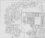
1.JPG

The circles with red color are those that I was referring to. (of course there are other, but just to make the example valid I have selected those) The green circles represent other ground.

Perhaps I am confused, and if I am mixing all up I would appreciate that someone could explain me what are the differences and in case that I want to measure the voltage at the capacitor C720 how could I do it.
 

Re: Reading the TV schematic

The one on the left side shouldn't be there, it looks to be an error on the schematic. The others are OK, they are all on the secondary side of the transformer.

You sometimes see high value resistors or low value capacitors between the primary and secondary sides but these are always safety rated high voltage parts and are there to provide a tiny current leakage to prevent high voltages building up on the secondary side.

Measure C720 across it's pins, the negative side is chassis ground. what you have to be specially careful of is measuring anything on the primary side of the PSU as it has no safety isolation from the incoming AC. Likewise, don't try to measure anything with one probe on the prmary and one on the secondary side as there is no direct connection between them to provide a common reference point.

Brian.
 

Re: Reading the TV schematic

Hello there betwixt. Thank you very much for your answer.

So, you think that the symbol that is at the negative pin of the input capacitor C705 is wrong. It shouldn't be there. Is that it? If so, there is no ground on the primary?

There another symbol on the schematic, that looks like a triangle. What is for that symbol? What are the main differences between the symbol at the negative pin of C705 and that one that looks like a triangle?

Another question, the high-voltage transformer is at the secondary side of the PSU?

BTW, for what purpose is the other primary inductor at the primary side?

To finish, if you notice, there is another half-bridge, that is pulled out right after the common-mode rejection transformer. In that case, that side is on the primary side or at the secondary side? I ask that because, if you notice again, we can see, for example, in the filter capacitor C724 that the negative side is connected to the ground symbol that is suppose to be for the secondary side of the transformer. Right?

Best regards and thanks in advance.
 

Re: Reading the TV schematic

Lots of questions....

In some exceptional circumstances, the TV chassis can be connected to one side of the rectifier bridge (D701 - D704) but it is very rare because it makes all the metal parts dangerous to touch and all exposed parts have to be individualy isolated, including the antenna socket, AV sockets and headphone socket. It is far easier to isolate the TV from the incoming AC so they can all safely be connected to other equipment without additional isolation. Note that it isn't ground in the sense of the Earth beneth your feet or an Earth pin on an AC socket, if you connected to one of those you would short out the incoming AC and blow the house fuses (hopefully!). I think it's an error on the schematic.

The chassis and triangle are different gounds, kept apart from each other to prevent signals crossing into each others circuits. If you look closely, they are actually linked together at J701.

Be careful when referring to the primary and secondary sides of the PSU. In general, they refer to the side connected to the incoming AC (primary) and the isolated output powering the rest of the TV (secondary). When referring specifically to a transformer they are the windings providing the magnetic flux and the the windings tapping into it. The high voltage winding is between pins 12 and 17 and the feedback winding to keep it oscillating is between pins 14 and 15. All the other windings are on the secondary side of the supply and produce the various voltages needed in the other circuits of the TV. This looks like a CRT TV so there will be another transformer somewhere to generate the 25KV or so to drive the tube.

D707 and D708 are a low current supply to keep IC702 running and all the circuit around there is on the primary side of the supply. IC702 has to be powered all the time because it reads the switches on the TV, including the standby switch and also reads the remote control signals. If it were to be powered down it wouldn't be possible to turn the TV on!

Brian.
 
  • Like
Reactions: AMSA84

    AMSA84

    Points: 2
    Helpful Answer Positive Rating
Re: Reading the TV schematic

Hello again betwixt.

I am sorry, but I have forgotten to put the other part of the schematic that has the high-voltage. Of course, I know what is the primary side and the secondary side. When I asked if the the high-voltage transformer is at the secondary side of the PSU? I was referring if that high-voltage transformer, that generates the 25kV, is at the secondary side of the T701, since that you said that the symbol that is at the negative side of the capacitor C705 (that is an error) belongs to the secondary side, and on that part of the high-voltage transformer we have that same symbol. Please, see the figure below.

About that feedback winding, how that winding is used to oscilate? What makes the transformer oscillating it is not the IC702?? I can not understand that winding. Could you explain me?

Another question, about the D707 and D708, is if that part is on the primary side or in the secondary side? I ask that again because, as you can see, there is again that symbol that you said that is referred to the secondary side of the transformer. If so, the high-voltage transformer (25kV) is at the secondary side of the PSU right? Do you understand what I am trying to say?

The last question, but not the least: In some exceptional circumstances, the TV chassis can be connected to one side of the rectifier bridge (D701 - D704) but it is very rare because it makes all the metal parts dangerous to touch and all exposed parts have to be individually isolated, including the antenna socket, AV sockets and headphone socket. In this case, how can I see if this TV has the chassis connected to one side of the rectifier bridge?

BTW, were you would suggest me to connect the negative side of the multimeter in the primary side and on the secondary side in order to make some measurements?

All the best and thank you again very much.


2.jpg
 

Re: Reading the TV schematic

You have o understand why this kind of PSU is used at all. Firstly, it is more efficient, less heat is generated by using switching rather than linear regulation, secondly, the high switching frequency allows smaller transformers to be used. A transformer with independent windings also gives you an isolation barrier between parts connected to the incoming power cord and the 'consumer' side of the TV. There are some TVs that use a floating chassis principle where the AC is rectified and the negative side goes straight to chassis. These TVs have a serious drawback, none of the extrnal connections on the TV are isolated from the AC cord except by a diode and are therefore very dangerous to touch or connect to other equipment.

Consider for example that you have a DVD player and it's chassis is connected to earth for safety as almost all do. Now think what would happen if you connected it to an AV socket on the TV and the negative side of C705 was connected to chassis. You would short out the AC through L701 and the diodes and blow your house fuses. even worse, if the DVD player did not have an earthed case, it would become live and dangerous to touch. Isolating the PSU is far more econmical than isolating every other connection on the TV, this is why I think the chassis connection to C705 is an error on the schematic.

The normal way a PSU like this works is the entire TV after the power transformer is isolated from the AC power side by the PSU transformer, which is T701 on your schematic. You may note that even the voltage regulation feedback is isolated by using opto-coupler IC705. The same schematic error appears in other places, for example at the bottom of the schematic where R700/701 and C770 are apparently shorted out. The person drawing the schematic has made no distinction between the negative side on the primary and secondary sides of the transformer.

To measure voltages in the AC (primary) side, your voltmeter should be connected to the negative side of C705. to measure voltages on the secondary side, connect it to the negative side of C718 although this is probably also connected to most of the exposed metalwork in the TV.

I doubt IC702 has anythng to do with the oscillation, it's far more likely to just be a monitoring device that reads the TV switches and the remote control signals. I think the signal from PA1 is just an off/on control to the PSU oscillator. The other controls volume/brightness/channel etc. are optically coupled through IC704 to the remainder of the TV.

The PSU oscillator itself is formed by using Q701 to switch the rectified AC power across pins 12 and 17 of T701. A small amount of the signal is picked up by the winding between pins 13 and 15 which is then fed to the gate of T701 to maintain the oscillation.

The 25KV is produced by T601 which in turn is fed by the 150V rail from the main PSU.

Brian.
 

Re: Reading the TV schematic

Hello brian. Thank you very much.

The T601 is at the secondary side of the T701?
 

Re: Reading the TV schematic

Yes, it is fed from the 150V supply from D720 on the secondary side of T701.

Brian.
 

Re: Reading the TV schematic

yes there seems to be something wrong in the ground markings in the schematic.
In a SMPS power supply you cannot mix the primary and secondary grounds.
Observe the connection of capacitor C770 a 3300pf 4kv rated capacitor to be connected between the primary and secondary grounds
both ends are shown connected to same side !!
It will be safer to use an isolation transformer(1:1) when servicing this TV chasis
 

Re: Reading the TV schematic

That isolation transformer is to connect what? Instead of the TV being connected directly to 220V, it is better to connect first to that isolation transformer and them the transformer to the 220V?
 

Re: Reading the TV schematic

yes thats right, you connect the TV to the isolation transformer and the transformer
is connected to the mains
you can then even touch the chasis while energised as there is no neutral/phase connection of the mains supply to the chasis
A approx 200 watts rated isolation transformer will do.
Anyway what is the problem in the TV set?
 

Re: Reading the TV schematic

Well, I have quite from trying to repair it.

At first, the TV didn't turned on. I replaced the fuse, for the same rating. When I turned it on, the fuse got blown.

So I opened the TV and I notice that the MOSFET, a zener, a small transistor (maybe the one used to drive the MOSFET), a capacitor, a low value resistor and the vertical transistor, I mean, the high-voltage TJB were broken. So I replaced them and when I was about to turn it on, the screen gone blue. At first, there was that typical image (black and white) and the sound. After 2 second, the TV gone mute and right after the image gone blue.

I read that it could be bad contacts, color transistors (the TV doesn't have those traditional transistors for the RGB, instead, has a TDA), connections that might be in open-circuit, etc.

So what I did? I reviewed all the connections and re-soldered the contacts that I thought that were important. When I turned on again the TV, the fuse literally exploded. There was a flash.

Well, I though, "I might have done a short-circuit". So I reviewed all the soldering contacts, even with an electronic microscope, cleaned up all the board with alcohol and a brush-teeth and replaced all the same components that were broken from the first time (strange, were the same basically). Apart from that, I don't know if anything else had broken, but I measured almost ALL the components in the PSU and some other in the rest of the circuit and they were OK.

Then, I turned the TV on and nothing have happened. The TV is on, but nothing happens. I haven't done any kind of measurements because I don't have much experience with this kind of device and because one time that I've replaced all the components I tried to do some measurements and the fuse had blown. I don't know if I did some mistake or what. Another reason is, of course, because the high-voltage component that the PSU has.

One last thing that I did was to verify the uP that I think controls the MOSFET. As you can see, is represented by the IC702 in the first schematic. I got him out of the board (it's a SMD compnent) and what I saw? The tracks in bad conditions! I have tried to do something in order to get around that and I have soldered that on a stripboard very carefully. I soldered on the corresponding place on the IC tracks but in another holes that were linked to the corresponding IC pins. Nothing happened.

I don't know if it's from that IC702 or what, so I gave up. Beside that, I don't know if that IC is easy to find.

Regards.
 

Status
Not open for further replies.

Part and Inventory Search

Welcome to EDABoard.com

Sponsor

Back
Top