Continue to Site

Welcome to EDAboard.com

Welcome to our site! EDAboard.com is an international Electronics Discussion Forum focused on EDA software, circuits, schematics, books, theory, papers, asic, pld, 8051, DSP, Network, RF, Analog Design, PCB, Service Manuals... and a whole lot more! To participate you need to register. Registration is free. Click here to register now.

Reading a SPI sensor over a long distance

Status
Not open for further replies.

nickagian

Member level 4
Joined
Mar 19, 2009
Messages
71
Helped
2
Reputation
4
Reaction score
2
Trophy points
1,288
Location
Zurich, Switzerland
Activity points
2,001
Hi folks and Merry Christmas!

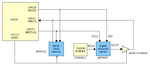
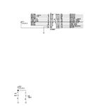
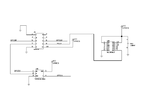
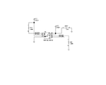
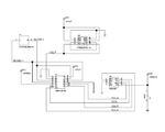
Attached is my schematic. As you can see I use the uC SN250 as SPI master for reading data on the same bus, both from an SPI memory (M25P128) and a SPI pressure sensor (MS5540C). The 74AHC1G126 3-state buffer is because the sensor does not have any CS# line. When GPIO3 is LOW, then the flash memory is enabled for communication and the buffer is in high-Z, whereas when GPIO3 is HIGH, then the buffer is enabled and communication with the sensor an be performed. The SG303LC oscillator provides a clock necessary for the operation of the integral ADC of the sensor. All components are included on the same PCB except for the sensor, which is 3m away. The problem I experience is that the SPI bus seems not to be working correctly, when this long twisted and shielded 3m cable is connected. On the contrary, if the sensor is put very close to the PCB (20cm cables) everything works fine.. When the sensor is connected so far away, I can neither read from the sensor neither read from the memory correctly. Is it possible that the long cables by their own produce such a serious problem? Are you aware of any maximum distance for the SPI bus? Do you have anything else to propose as the reason for this problem?

Thanks!
 

Attachments

  • SPI_connections_v2.PNG
    SPI_connections_v2.PNG
    12 KB · Views: 120

I wouldn't expect the SPI to work with long cables. The problem is likely to be that you get ringing and the edges get distorted. If you have an oscilloscope then am sure you would see a horrible mess if you looked at the SPI lines.

I guess you could try buffering the signals, although adding some pull-up or down resistors may clean it up enough to make it work.

Keith

Hi Keith and thanks for answering!
Well, I did look the signals with the scope and the problem is that I didn't find anything wrong. They seemed normal to me. However, I'm not very experienced and thus they may indeed suffer from distortion. Hm.. giving a second thought, I checked the signals on the main PCB and not at the far end. I think that I have to give them a second look on the scope. Nevertheless, if we guess that the signals at the PCB did indeed seem to be good and that at the far end they were like a mess, does this explain why I cannot read correctly from the flash, which is on the main PCB?

Regarding putting pull-up/pull-down resistors, I cannot understand why that could make the situation better. And where should I put them? At the main PCB, at the point where the lines are leaving?

I have attached the schematic. Page 4 contains the remote PCB where the sensor (along with some other analogue sensors) is soldered on. The other pages are the main PCB. Page 1 is the uC, page 2 is the buffer and the oscillator and page 3 is the flash memory. The supply voltages may have different names, but they are practically the same. They just come through different analogue power switches.

As you can see, I have indeed put some pull-ups at the clock and the CS# signals, but none at the MOSI/MISO.
 

Attachments

  • schematic_p1.PNG
    schematic_p1.PNG
    21.5 KB · Views: 114
  • schematic_p2.PNG
    schematic_p2.PNG
    17.8 KB · Views: 112
  • schematic_p3.PNG
    schematic_p3.PNG
    13.5 KB · Views: 111
  • schematic_p4.PNG
    schematic_p4.PNG
    21.7 KB · Views: 106

The problem with the signals could simply be slow rise/fall times. They might not look too bad but as the chips could be quite fast they may double trigger with a slow edge.

It is only a guess with the pull-ups, and not an ideal solution but something like a 1k resistor on all the lines at both ends may help. It would be better if you could 'see' the problem on the signals then you know what you are trying to fix.

Keith

I see what you mean.. ok then, I'll try to examine the signals in more detail and come back if I have found anything new. Thank you very much for your help!

Nick
 

Hi again!

I have made some measurements with the scope. I attach here some pictures.
FIGURE 0 shows the rise time of SCLK measured at the main PCB, when the remote sensor is connected (it was found 170ns)
FIGURE 1 shows the rise time of SCLK measured at the remote PCB, at the sensor (it was found to be 140ns)
FIGURE 2 shows the rise time of SCLK when the remote sensor is not connected (it was found to be 33ns)

Is it possible that this increase to the rise time of the clock can create the inability of the processor to reach the SPI devices? I cannot understand (in fact I don't know it at all) why the increase of the rise time of this signal can lead to the device being inaccessible.

Is there any way to solve this issue of the rise time (without the need to use a buffer)? Which else signal should I measure with the scope?

nick
 

Attachments

  • FIG0_SCLK_flash.PNG
    FIG0_SCLK_flash.PNG
    8.5 KB · Views: 109
  • FIG1_SCLK_sensor.PNG
    FIG1_SCLK_sensor.PNG
    7.7 KB · Views: 99
  • FIG2_SCLK_no_sensor.PNG
    FIG2_SCLK_no_sensor.PNG
    6.1 KB · Views: 92

No clock ringing shows up so far, but the signal may look different without the oscilloscope probe connected- Sometimes connecting a probe makes the system work again. Additionally, the CLK to CS and DATA timing should be checked, but the clock seems to be rather slow, so most likely the timing isn't critical. I assume, that the correct SPI modes (e.g. 0 or 3 for M25P128) are used. The M25P128 is an example of these fast devices Keith mentioned, the minimum clock rise time is specified by 0.1V/ns which is clearly violated in the long distance situation. Placing a schmitt-trigger buffer near the SPI device would be a straigthforward way to keep the specification. 74LVC1G17 would be a suitable single-gate part.
 

Status
Not open for further replies.

Similar threads

Part and Inventory Search

Welcome to EDABoard.com

Sponsor

Back
Top