Continue to Site

Welcome to EDAboard.com

Welcome to our site! EDAboard.com is an international Electronics Discussion Forum focused on EDA software, circuits, schematics, books, theory, papers, asic, pld, 8051, DSP, Network, RF, Analog Design, PCB, Service Manuals... and a whole lot more! To participate you need to register. Registration is free. Click here to register now.

rc CIRCUIT Intuitive analysis

Status
Not open for further replies.

kunalbansal52

Newbie level 4
Joined
Jun 25, 2010
Messages
5
Helped
0
Reputation
0
Reaction score
0
Trophy points
1,281
Activity points
1,333
hii , I have a problem in understanding how to solve RC circuits intuitively . I have the Orcad pspice code with me . It is as follows


Simple RC circuit
Vs 1 0 PWL(0 0 .001 1 15 1)
R1 1 2 1
C1 1 2 2
R2 2 0 3
.TRAN .01 15
.PROBE
.END

graph.png

Please explain me given that based on the graph I uploaded , it says that Capacitor is zero initially then charges to corresponding proportion of Vs . Can you please explain me how to come to this solution intuitively
 

First, imagine the circuit in steady state --> Then the cap does not exist and the voltage at node 2 will be Vcc*R2/(R1+R2) = 3/4 = .75V

Now, analyze the behaviour when t=0+ --> The cap voltage is still 0, then the voltage at node 2 will be 1V.

Finally, the cap will go charging slowly until the steady value. And the time constant will be T=Rv*C, with Rv the R view by the cap ( Rv=R1R2/(R1+R2) )

@eduardo :- thnx for this explanation , But i have doubt in understanding that how to analyze the behaviour at t=0+ ?? as in if there are multiple capacitors in the circuit then how we must analyze it at t=0+ . In the steady state we understand that capacitor is open ,so not a problem but in t=0+ how to do it ? It would be a gr8 help to me , if you please explain it .
 

There's no initial voltage or current present in the circuit, thus all energy storage devices hold zero energy. Vcapacitor and Iinductor are initially zero and can only grew continuously.
 

@eduardo :- thnx for this explanation , But i have doubt in understanding that how to analyze the behaviour at t=0+ ?? as in if there are multiple capacitors in the circuit then how we must analyze it at t=0+ . In the steady state we understand that capacitor is open ,so not a problem but in t=0+ how to do it ? It would be a gr8 help to me , if you please explain it .
At t=0+ the voltage at capacitor is the same at t=0- because Ic = C dV/dt ==> the voltage at C is a continuous function.

Try the same circuit with same step but with initial condicitions (ie Vc = -10V and Vc = 0.25V)
 

In case this might further intuitive understanding...

I have a Youtube video which visually portrays capacitor behavior.

Various waveforms are applied including pulsed DC.

It shows volt level on the capacitor, plates charging/discharging, current bundles traveling through wires.

www.youtube.com/watch?v=eIWEU4pObJw
 

I have another doubt , an extension of this ... I tried to put a diode in the RC circuit and tried to analyze . Can you please explain me for the following example how to get the result in the graph attached herewith intuitively . It would be a great help , please explain it . And also If there is any reference where I can learn how to analyze these type of circuits intuitively please do mention it . Here is the following PSpice code

Vs 1 0 PWL(0 0 .001 1 15 1)
C1 1 2 2
R1 3 0 2
D 2 3 DMOD
.MODEL DMOD D(Is=10n N=2)
.TRAN .01 15
.PROBE
.END

The graph is
graph1.png
 

Hi kunalbansal52,

PSpice isn't exactly the best tool to gain an intuitive understanding for electronics. It is much better to go into a lab and play with actual components, and then contemplate the circuit behavior (the voltages, the currents, and the link between them) in an attempt to internalize and understand it. PSpice wasn't made for assisting an intuitive understanding at a fundamentals level; it becomes useful for understanding at a more advanced level, once you're already familiar with fundamental circuit behavior.

Thankfully, there exists a circuit simulator which was built specifically for assisting the sort of intuition you're attempting to build: Falstad's Online Java Circuit Simulator. This simulator has animations to help you envision the charges moving, and the voltages that push them. He has a large collection of circuits you can simulate, and you can even draw your own circuits. I suggest you play with his simulator for a few weeks.

Hope this helps.
 

Hello ZekeR,
if I remember well - it was quite often that I could agree with you.
However, today I can't.
For my opinion, the Falstad animations show nothing else than something that shall represent a current within a circuit.
Please, tell me what should someone learn from these simplified animations? There are no explanations at all.
For example, is it interesting to see how the current changes direction while it is flowing through the various parts of an oscillator circuit?
Similar arguments hold for most of all other circuits (I didn't check all).

In contrast to you I think, all classical circuit simulators (like PSpice) are extremly good tools to learn how and under which conditions a circuit operates. Even for beginners.

Regards
LvW

Quote ZekeR: I suggest you play with his simulator for a few weeks.

I am afraid, this would be a waste of time.
 

Thankfully, there exists a circuit simulator which was built specifically for assisting the sort of intuition you're attempting to build: Falstad's Online Java Circuit Simulator. This simulator has animations to help you envision the charges moving, and the voltages that push them. He has a large collection of circuits you can simulate, and you can even draw your own circuits. I suggest you play with his simulator for a few weeks.

Hope this helps.

Dozens of posts here have linked to Falstad's animated simulator, or have used it to draw schematics, or referred to it as a helpful aid.

I can say it has furthered my understanding of electronics. More so as I've been constructing circuits with it (since earlier this year).

Who hasn't said "I wish I could put an ammeter in every wire, because that would really show what's going on."

But I didn't find a computer simulator that lived up to that goal.

I said to myself, "Why not devise my own analog simulator?" So I've worked on my program for over 15 years.

And it has its shortcomings. Falstad's has its shortcomings. However both mine and his are designed to do things I have never seen any other simulators do. These are aids to understanding, and it's hard to argue with anything that aids understanding.

Even the simulators favored by professionals reputedly have their shortcomings.
 

.........................
Even the simulators favored by professionals reputedly have their shortcomings.

Yes, of course. But do you really try to compare this "animation" with our classical circuit simulators ?

Hi BradtheRad,

speaking about a "waste of time" of course, I mean: If compared with other sources of information like textbooks.

Let me explain:
On Falstad's pages mostly a circuit is shown with a lot of moving points only - illustrating the current flow. I doubt if such an animation carries a lot of new information.
Parts values cannot be modified. In addition, sometimes some rough descriptions are given - no real explanations.

In contrast, I think the main advantage of the classical simulator concept is that the user is forced to design the circuit before its behaviour can be simulated in the time or frequency domain.
That means, he has to arrange the parts by himself, to fix component values and to decide which parameter he wants to visualize (currents, voltages,..).
And - last but not least - if something is not in accordance with his expectations (expectations are very important!) he feels the necessity to start thinking again in order to find the reason.
The whole process is a very fruitful way of learning and understanding; it can be called "inter-active circuit simulation" - in contrast to Falstafs "passive watching of animation".

Do you know what I mean?
Regards
LvW
 

I agree that we learn far more if we can participate, by changing values and watching how it affects the action.

The passive spectator role is not nearly so enlightening.

Although Falstad's simulator takes a bit of time to 'work through the quirks', I am happy to report that you can indeed change component values. Results are immediate.

This can be done both (a) running the applet at the website, or (b) running the circuit simulator from your hard disk (after downloading it).

Windows machines: Right-click, edit values in the window, and click OK.

Macintosh: Control-click, etc.

To move components around: Press keys such as Command, Control, Alt, Option, spacebar, etc., and drag them with the mouse.

Recently I found that it can generate a link containing an entire circuit. Clicking it will open the falstad.com website, and run the circuit on your computer.

I constructed a Cockcroft-Walton voltage doubler. Looking at a schematic we only have a faint notion what goes on through a cycle. Even looking at static scope readouts doesn't really tell us what's going on.

This is an animated portrayal.

Link follows. Click 'OK' to run the Java applet.

You'll find you can edit components at will. Two moving scope traces show the charge levels on the load capacitors.

https://www.falstad.com/circuit/#$+...0+35+20.0+0.8+0+-1 o+5+64+0+35+20.0+1.6+1+-1
 

LvW, Falstad's simulator indeed does allow one to edit component values and create new circuits.

I agree that designing a circuit yourself is generally more effective than loading a pre-made one, especially with regards to matching expectations, and in this respect his large collection of pre-made circuits may discourage some of the activities that really ought to be performed by a budding circuit designer. In addition, because his program's interface discourages quantitative analysis, the exact quantitative relationships may go unnoticed.

In my opinion, however, one should concretely learn the qualitative relationships before attempting to tackle the quantitative. I have seen all too often, engineering students who are faced with quantitative analysis without even the slightest notion of the qualitative behavior; their engineering is usually mediocre, as they must resort to memorizing equations (the derivation of which is abstract to them). A "qualitative" understanding is largely visceral and intuitive: having a sense of imagination as to how the circuit will behave, not strictly according to equations, but according to physical forces and motions: much as one might imagine water traveling through pipes, or waves crashing on a beach. The largest hurdle in intuitive understanding for electronics is the very first one: being able to "see" the physical phenomena underlying electrical behavior, since it is invisible. And here is where Falstad's simulator brings its greatest worth, by animating the invisible and making the circuit come to life. (There is much to be said here for spending time in an electronics lab, as well.)

Once one has built a good, visceral sense for the physical phenomena, then it becomes easier to see the life in a graph of voltage versus time. Much like a musician fluidly sways his hand in synchronicity with the sheet music he is reading (while the music plays in his head), an electrical engineer naturally comes to envision voltages and currents dancing in the circuit. The musician can only read sheet music if he already has experience with what the notes will sound like, and likewise the engineer can only envision the circuit's behavior once he has "seen" how the elements behave.

So, for the sake of learning an intuitive understanding, I think Falstad's simulator has something to offer. By animating the invisible, it makes the abstract tangible. We teach children that an electron is a particle orbiting its nucleus like a planet orbits the sun, rather than describing an electron as a particle-wave existing within a probability cloud, for the same reason. Once they have a solid grasp of the basics in a manner that seems concrete to them, then we can move on to more abstract concepts; if we instead attempt to teach them the "truth" upfront, then it is likely that they will not retain it, and they will resort instead to memorizing equations.

Eventually, the training wheels do become a hindrance and one would be wise to "outgrow" Falstad's simulator. Perhaps playing with his simulator for a few weeks is too much, but at least a few days would be helpful.
 

LvW, Falstad's simulator indeed does allow one to edit component values and create new circuits.

In my opinion, however, one should concretely learn the qualitative relationships before attempting to tackle the quantitative. I have seen all too often, engineering students who are faced with quantitative analysis without even the slightest notion of the qualitative behavior; their engineering is usually mediocre, as they must resort to memorizing equations (the derivation of which is abstract to them). A "qualitative" understanding is largely visceral and intuitive: having a sense of imagination as to how the circuit will behave, not strictly according to equations, but according to physical forces and motions: much as one might imagine water traveling through pipes, or waves crashing on a beach. The largest hurdle in intuitive understanding for electronics is the very first one: being able to "see" the physical phenomena underlying electrical behavior, since it is invisible. And here is where Falstad's simulator brings its greatest worth, by animating the invisible and making the circuit come to life. (There is much to be said here for spending time in an electronics lab, as well.)

Once one has built a good, visceral sense for the physical phenomena, then it becomes easier to see the life in a graph of voltage versus time.

So, for the sake of learning an intuitive understanding, I think Falstad's simulator has something to offer. By animating the invisible, it makes the abstract tangible.

BradtheRad and ZekeR, thank you for responding.

OK, I didn't know that - and now I have learned - that Falstad's simulator indeed allows component editing. Fine.
And I totally agree with all of your arguments regarding the sequence of qualitative and quantitative understanding (I also have some experience in education of engineers).
Nevertheless, I still have some doubts if this simulator really can do that - that means: generate "a good, visceral sense for the physical phenomena" (quote ZekeR).
Just some examples (although I must confess that I didn't check all circuits provided by Falstad):

*BJT function: I didn't find any place where the newcomer can see and learn that the physical operation of a BJT consists of a voltage controlled current source. You know about the common misconception that a small current (base current) would control a large current (collector current).

*Feedback: One of the most important working principles in analog signal processing is the principle of feedback. I didn't find any explanation or demonstration what feedack is and how it works.

*Common emitter stage: The purpose/function of the emitter resistor Re is not explained at all.
More than that, the electronics newcomer learns that the gain is equal to the ratio Rc/Re. Does this "information" support a qualitative understanding? In contrast, I think it is a quantitative - and false - statement.

*Opamp amplifiers: The principle of feedback is covered with the sentence: The op-amp attempts to keep its two inputs at the same voltage. Is this really enough to explain quantitatively the physical principle of negative feedback?

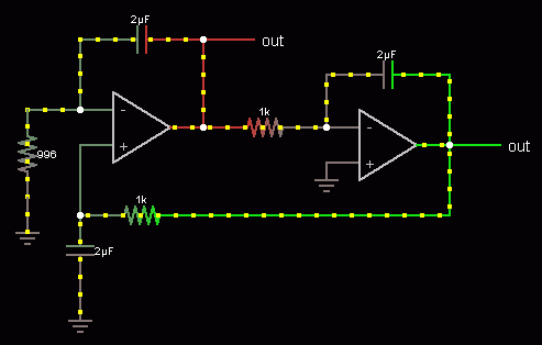
*Oscillators: A two-integrator oscillator is shown together with animated points (currents) and the sinusoidal output. No mention of the general oscillation condition (based on loop gain). All resistors are 1k - except one (996 ohms). Why? I think, at this point the working principle of this oscillator was not correctly understood by the originator - and this can lead to a false understanding on students side because this circuit works the same way also with all resistors R=1k.
_______________________________________________

Perhaps I am wrong, but I am afraid that this software from Falstad can lead to a sight/understanding of physical phenomena that is to simplified. That`s all.
Thank you and regards
LvW
 
Last edited:

*Oscillators: A two-integrator oscillator is shown together with animated points (currents) and the sinusoidal output. No mention of the general oscillation condition (based on loop gain). All resistors are 1k - except one (996 ohms). Why? I think, at this point the working principle of this oscillator was not correctly understood by the originator - and this can lead to a false understanding on students side because this circuit works the same way also with all resistors R=1k.

The simulator shows a very slowly decreasing oscillation magnitude when changing the resistor form 996 to 1k. The point refers to real versus ideal component models used in simulation. In my view, the resistor asymmetry is used on purpose and will in fact cause an increasing oscillator magnitude (up to OP the saturation limit), creating stable oscillator operation conditions. With real OPs, the additional poles will achieve the same using equal resistors.
 

The simulator shows a very slowly decreasing oscillation magnitude when changing the resistor form 996 to 1k. The point refers to real versus ideal component models used in simulation. In my view, the resistor asymmetry is used on purpose and will in fact cause an increasing oscillator magnitude (up to OP the saturation limit), creating stable oscillator operation conditions. With real OPs, the additional poles will achieve the same using equal resistors.

Hi FvM,

interesting question, which deserves - for my opinion - an extra thread. But I don't know if you and/or some others are interested. You are touching the oscillation condition of the double-integrator oscillator, which - as far as I can see - is not solved yet finally. That means: There remain two questions which are not yet answered:
1.) Why and at which percentage of clipping is the oscillator amplitude stabilized? For all other oscillators with a frequency-dependent feedback path and a gain unit this can be answered using the concept of excess gain (loop gain > 1) - in some cases together with the concept of harmonic analysis. But this does not work for the oscillator under discussion.
2.) Assuming that there is a frequency fo that fulfills the oscillation condition (loop gain=1) - why does this oscillator not oscillate at one or some other frequencies below fo (because the loop gain magnitude>1 and the phase condition is fulfilled also for f<fo) ?
Remember: All other oscillators do that as long as the magnitude of the loop gain is larger than 0 dB (and the loop phase=0)
______________

Back to our case: I agree with you that there are decaying oscillations if the mentioned R also has 1k. However, the same applies also for 996 ohms.
The answer is simple: For ideal opamps the phase reaches 0 deg for infinite frequencies only.
This allows the following statement: A working two-integrator oscillator requires real opamps. For ideal opamps (and no additional external phase shifting devices) no continuous oscillations are possible.
Simulation results (1k, 2uF) and ideal opamp (Ao=1E5):
R=1k (0.996k) : Loop gain cross-over at 79.58 Hz (79.75 Hz), Phi=0.00115 deg. (0.00116 deg).

This result confirms that in both cases the oscillation condition is not fulfilled.

So - what happens if one modifies the time constant of one integrator? Answer: The cross-over frequency is shifted and because of that the possible oscillation frequency. That is the only effect.
By the way: You can design such a two-integrator loop also for completely different time constants. The oscillation frequency is wo=1/SQRT(T1*T2).

That was the reason I have mentioed that it is unnecessary to choose 996 ohms for this resistor. This does not help at all to start oscillations.
Finally, one has to realize that this kind of oscillator is the only one that exhibits a (nearly constant) loop phase function and a frequency depending loop gain magnitude.
This is in contrast to all other oscillator topologies (as far as I know) and, therefore, requires some other explanations.
Sorry, originally it was not my intention to write such a long contribution.
Regards
LvW
 

I'm generally interested in this discussion, but I didn't want to start it in this place. If I remember right, there's a still pending question of yours (several years old) in a previous thread.

For the present oscillator circuit, I thought to come off with a narrower view. By nature of the BTC ("balanced time constant" non-inverting) integrator, the 996R resistor does not only change the integrator time constant but also introduces a small deviation from ideal integrator behaviour.

Referring to a general harmonic oscillator equation https://en.wikipedia.org/wiki/Harmonic_oscillator it causes a small negative damping ratio in the overall behaviour, just what's required for a real oscillator to start oscillations.

The modification corresponds to the "additional external phase shifting devices" addressed in your post.

In other words, the modification seems resonable from an empirical engineering viewpoint. Although you can't know if the author fully understands the working principle of the circuit, I would suppose it for the time being.
 

For the present oscillator circuit, I thought to come off with a narrower view. By nature of the BTC ("balanced time constant" non-inverting) integrator, the 996R resistor does not only change the integrator time constant but also introduces a small deviation from ideal integrator behaviour.

Aahh - I see what you mean. However, in Falstad's oscillator it is NOT a resistor in the BTC integrator but in the Miller integrator that is reduced to 996 ohms.
Thus, my arguments still hold.
More than that, it is true that a certain unbalance (imbalance?) within the BTC unit can force the phase to cross the 0 deg line - however it is very hard (impossible ?) to match this characteristic with the gain cross-over.
 

Aahh - I see what you mean. However, in Falstad's oscillator it is NOT a resistor in the BTC integrator but in the Miller integrator that is reduced to 996 ohms.
Thus, my arguments still hold.More than that, it is true that a certain unbalance (imbalance?) within the BTC unit can force the phase to cross the 0 deg line - however it is very hard (impossible ?) to match this characteristic with the gain cross-over.

In the below circuit, the resistor variation is in the BTC integrator. It causes a lag/lead term centered at the oscillation frequency, in so far it's supposed to achieve the intended purpose.

98_1341141207.gif


But I must confess, that this is just my "intuitive" view on the circuit, without exact analysis.
 
  • Like
Reactions: LvW

    LvW

    Points: 2
    Helpful Answer Positive Rating
In the below circuit, the resistor variation is in the BTC integrator. It causes a lag/lead term centered at the oscillation frequency, in so far it's supposed to achieve the intended purpose.
.
Sorry, you are right. I cannot understand why I was of the opinion the 996 ohm resistor would belong to the Miller unit.
Perhaps the reason is the following (simple but painful): In most cases - when I draw a circuit like the one under discussion - I place the simple Miller integrator to the most left side. My fault.

As a consequence, I have to reformulate my statement (in bold) in post#16:
A working two-integrator oscillator - without some additional means to add phase lag - requires real opamps.

Thank you for correcting me.
 

Status
Not open for further replies.

Similar threads

Part and Inventory Search

Welcome to EDABoard.com

Sponsor

Back
Top