Continue to Site

Welcome to EDAboard.com

Welcome to our site! EDAboard.com is an international Electronics Discussion Forum focused on EDA software, circuits, schematics, books, theory, papers, asic, pld, 8051, DSP, Network, RF, Analog Design, PCB, Service Manuals... and a whole lot more! To participate you need to register. Registration is free. Click here to register now.

ramp generator using opamp

Status
Not open for further replies.

mshh

Full Member level 6
Joined
May 30, 2010
Messages
349
Helped
0
Reputation
0
Reaction score
0
Trophy points
1,296
Location
usa
Activity points
3,871
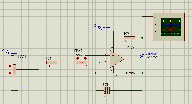
i need to know if this circuit is working for the generating ramp signal ? i can't see it on oscilloscope it gives constant signal after delay in the beginning.


What you have there, my friend, is an integrator. When you apply power it should ramp up until it reaches its maximum and then stay there. And I'm not sure why you have that 1K resistor on the output, that's only going to waste power and not much else.
 

The 1k pullup resistor at the output prevents the opamp from producing crossover distortion because the lousy old LM358 is one of the first Low Power opamps with its output transistors starved for current in class-B instead of being in class-AB.
 

Attachments

  • ramp with crossover distortion.png
    ramp with crossover distortion.png
    5.7 KB · Views: 68

The 1k pullup resistor at the output prevents the opamp from producing crossover distortion because the lousy old LM358 is one of the first Low Power opamps with its output transistors starved for current in class-B instead of being in class-AB.
so what is the problem with this circuit?
 

You tell us. It's supposed to go to the rail and sit there. What do you EXPECT it to do?
 

it gives Vsat directly without ramp. i need it to increase gradually
 

The circuit is not a triangle-wave generator that needs to have an additional Schmitt Trigger opamp. A triangle-wave consists of TWO ramps, one going upwards and the other going downwards.
Here is a typical triangle-wave generator circuit:

- - - Updated - - -

it gives Vsat directly without ramp. i need it to increase gradually
With a negative input voltage then the inverting opamp output cannot saturate, instead it goes positive.
Here is your circuit without the messy grid lines:
 

Attachments

  • triangle-wave generator.png
    triangle-wave generator.png
    9.5 KB · Views: 137
  • integrator.png
    integrator.png
    6.5 KB · Views: 88

it s the same i can't see it while increasing . it just output Vsat directly
 

Then either your opamp is defective, or it's wired wrong. It should take tens of milliseconds for the output to rise.
 

How come I just got a Malware virus from this site that my AVG anti-virus software detected and removed?
 

The circuit is not a triangle-wave generator that needs to have an additional Schmitt Trigger opamp. A triangle-wave consists of TWO ramps, one going upwards and the other going downwards.
Here is a typical triangle-wave generator circuit:

- - - Updated - - -
co


With a negative input voltage then the inverting opamp output cannot saturate, instead it goes positive.
Here is your circuit without the messy grid lines:
when i use this circuit with two opamp . proteus stopped faild to start when i connect power to the schmitt trigger opamp
 

Frequently a simulated oscillator needs to have a KICK to get it started.
Maybe your integrating capacitor has backwards polarity?
 

Frequently a simulated oscillator needs to have a KICK to get it started.
Maybe your integrating capacitor has backwards polarity?
what do you suggest?
 

i tried ceramic capacitor , the same result . it gives vsat directly
 

i tried ceramic capacitor , the same result . it gives vsat directly
For sure.

If I understand right, your problem is not to understand how a circuit simulator works. There's a thing called initial transient solution. It will be performed by default unless you disable it explicitely. It calculates a circuit bias point for all initially applied circuit voltages and currents at t=0 with all circuit time constants ignored. Then start the transient simulation.

If you already apply a negative input voltage at t=0, the initial transient solution will bring the OP into saturation and start from this point. So no ramp generation happens during analysis.

Instead you would want to set the integrator input to zero during initialisation and keep the integration capcitor discharged by an .IC specification. Much more easily, just skip initial transient solution.

You surely had found the answer yourself by reading simulator user manuals or tutorials.
 

Status
Not open for further replies.

Similar threads

Part and Inventory Search

Welcome to EDABoard.com

Sponsor

Back
Top