Continue to Site

Welcome to EDAboard.com

Welcome to our site! EDAboard.com is an international Electronics Discussion Forum focused on EDA software, circuits, schematics, books, theory, papers, asic, pld, 8051, DSP, Network, RF, Analog Design, PCB, Service Manuals... and a whole lot more! To participate you need to register. Registration is free. Click here to register now.

radiation pattern in HFSS

Status
Not open for further replies.
Hey guys,

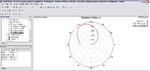
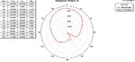
I managed to get some good results for the rad pat but with a small problem.

The E-plane rad pat seems to be shifted to the left a little, can someone please take a look at it? any ideas?

I've attached a snap shot for my rad pat, and the hfss file. Thanks :)
 

Attachments

  • 20120507_Balanis_solved Ex_optimized.zip
    12 KB · Views: 92
  • E-plan rad pat.JPG
    E-plan rad pat.JPG
    93.2 KB · Views: 101

I'd really appreciate if someone can take a look at my results above :)

Could this shift in the rad pat be because I chose Boundaries--> PerfectE--> "Infinite Ground" ?

I've attached a snap shot of my results before applying the Infinite gnd for your reference. Appreciating your feedback.
 

Attachments

  • E-plane rad without infinite gnd.JPG
    E-plane rad without infinite gnd.JPG
    58.1 KB · Views: 100

In the two pictures you are showing different values.
One times it is radio patter e and the other time it is radio patter h.

Can't you test the effect of the infinite ground by comparing a simulation with and without the ground?
 

I'd really appreciate if someone can take a look at my results above :)

Could this shift in the rad pat be because I chose Boundaries--> PerfectE--> "Infinite Ground" ?

I've attached a snap shot of my results before applying the Infinite gnd for your reference. Appreciating your feedback.


Hi Khaled,
i want the same results that it covers all the circle. but im nt getting the results like this what should i do?
i am using inf_ gnd. i am working on hfss v11, but their is no E & H plane defined. so step in result > far field > radiation pattern > -------------???- what should i select to see the graph which u have obtained.
i also want co & cross polarization.
Plz reply as early as possible

for theta i have selected 2 steps.

thanking u in anticipation
 

Have you set up the radiation boundary and the infinite sphere?
When you get a good 3d polar far field plot it should be ok.
For the 2d ration pattern you can sweep the theta angle at a fixed phi angle. You need more points than just two.
 

Have you set up the radiation boundary and the infinite sphere?
When you get a good 3d polar far field plot it should be ok.
For the 2d ration pattern you can sweep the theta angle at a fixed phi angle. You need more points than just two.

yes i have assigned radiation boundary & infinite sphere too. but didnt get results.

and 1 more height of GND plane affect on polarization ? if yes what should its value.

Thanking u in anticipation
 

Hi Chetali,

Have you checked my hfss file above? If you haven't still resolved your issue please let me know so I can help.
 

NO, i havent got my solution.
please, suggest its solution.

i changed inf_gnd to gnd so, im getting complete graph. but nt able to differentiate which is co and cross polarization.


Hi Chetali,

Have you checked my hfss file above? If you haven't still resolved your issue please let me know so I can help.
 

Hi Chetali,

Have you checked my hfss file above? If you haven't still resolved your issue please let me know so I can help.

can u plz solve my issue? im confused for E plane what is co & cross. becz u say 4 E & H plane gain phi & gain theta respectively . then wher is E plane co & cross ploz? n H also
 

Status
Not open for further replies.

Part and Inventory Search

Welcome to EDABoard.com

Sponsor

Back
Top