Xionarc
Newbie level 5

Hi All
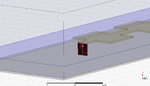
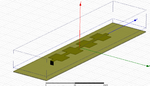
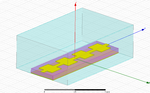
I've recently been playing around with planar leaky-wave arrays and in order to excite the LWA I use a Waveport which supports 2 modes- the dominant mode of the line and the leaky-mode of the radiating antenna. I think the Waveport matches the source/excitation with the impedance of the ENTIRE structure (patch antenna, substrate and ground plane together). When I use Waveport I get the right Leaky-Wave far-field characteristics that I want (from theory). However when I now use a lumped port between the patch and ground plane ( as a sort of point voltage source) where the lumped port is a rectangular sheet embedded inside the substrate, the far-field result is different.
I understand the waveport matches impedance completely while the lumped port needn't. Does that mean that if I solve for input impedance of the microstrip line patch antenna using the lumped port, and renormalized or changed the value of resistance and reactance of the lumped port to conjugate match the antenna input impedance, it still shouldn't matter? I was under the impression that if I excited the planar LWA at one end by both Waveports and Lumped Ports, specifying the right integration line to specify propagating mode, I should get the same result. My idea is to eventually match the lumped port and then substitute it with a load to see if I can detect a LWA incident wave.
I have the wave impedance of the wave propagating down the line (simulated in the waveport model) from the formula in pozar given by
Z=Zo [(1-2S11+S11*S22-S21*S12)/(1+2S11+S11*S22-S21*S12 )]^(1⁄2)
computed from the S parameters. Plotting this versus frequency gives a variation of wave impedance versus frequency. Whereas just plotting Z11 versus frequency should give me input impedance right? (for 2 modes there are Z(1:1,1:1), Z(1:2,1:1).....Z(2:2,2:2) and so on. )