Shayaan_Mustafa
Full Member level 5
Hello experts!
I have some question regarding with Op-amp.
Q#1) We know that we use Op-amp with closed loop not with open loop. But why we use negative feedback why don't positive feedback?
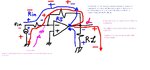
Q#2) Here is diagram of the simple Op-amp with feedback. We know due to high input impedance of the Op-amp the current flows through the feedback resistor as shown in the figure below. Right?

But when output is received(i.e. Vo) across RL then some part is fed back to the input in order to control the gain. Right? But the current flows in the reverse direction as shown in the figure below.

I am just confused how one feedback provides two way current, like this,
 Blue is current from output to input and Red is the current from input to output due to high input impedance
Does my thinking is wrong?
Thanks in advance.")
I have some question regarding with Op-amp.
Q#1) We know that we use Op-amp with closed loop not with open loop. But why we use negative feedback why don't positive feedback?
Q#2) Here is diagram of the simple Op-amp with feedback. We know due to high input impedance of the Op-amp the current flows through the feedback resistor as shown in the figure below. Right?
But when output is received(i.e. Vo) across RL then some part is fed back to the input in order to control the gain. Right? But the current flows in the reverse direction as shown in the figure below.
I am just confused how one feedback provides two way current, like this,
Blue is current from output to input and Red is the current from input to output due to high input impedanceDoes my thinking is wrong?
Thanks in advance.