ccarrot
Newbie level 6

- Joined
- Sep 19, 2007
- Messages
- 11
- Helped
- 0
- Reputation
- 0
- Reaction score
- 0
- Trophy points
- 1,281
- Activity points
- 1,399
Hi everyone,
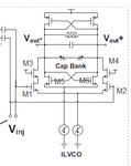
I'm designing an injection-locked LC-VCO with f0=2GHz. The circuit is shown bellow, this is a PMOS-NMOS crossed coupled LC-VCO, the injected signal Vij is put through M1/M2 differential pair. The Vij comes form a LNA in the previous part and a capacitor is in between the LNA and the VCO. I have some questions:
(1) The coupled capacitor between LNA and the VCO blocks the DC part, that means the Vij is a sine-wave with DC=0. Is that mean the M1/M2 need bias circuit?
(2) Why M3/M4 is put there?
(3) My design procedure is: first finish the LC-VCO, then design the injection differential pair. Am i right?
(4) I know that increasing the injected current will increase the locking range wL (let's say the input amplitude is constant), but no matter how big the current source (for the injection pair) is, or how large the W/L of the injection pair is (big gm), the locking range is always below 10MHz and looks like constant --- the locking range didn't increase. I even changed to another low-Q inductor, but the range still didn't increase. I don't know why this happen? and How to design this injection part properly?
(5) Is it true that if the VCO(freq is f0) is locked, when the Vij (freq is f1) comes, the output frequency is f1, but if Vij disappear, the output frequency will immediately come back to f0?
(6) I use Transient simulation to test it, however, it is time-comsuming. I don't know how to use PSS simulation to do the test because PSS always complain that there's periodic source there (injected sin-wave voltage source). Can anyone tell how to set up the PSS simulation for the IL-VCO?
Does anyone know this and can help me out? Thank you very much!
