emsensors
Junior Member level 3

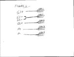
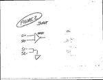
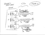
Hi, I am driving a coil at 10 kHz with a constant current source. There are two detector coils mounted axi-symmetrically positioned either side of the primary. All three coils have a resistance of 3 Ohms and inductance of about 275 uH (Figure 1). I am currently using foil shielded twisted pair cable for all three coils but I am having problems with noise when the cable is moved (presumably this is to do with the loop areas changing or changing coupling of the drive waveform into the secondary wires.) In the field, the cable is about 25m long and spliced to the shorter (1m) sensor cable but even in the lab with just the short sensor cable I notice a problem. I have a fairly simple input circuit (Figure 2) - the low side of the two secondary coils (S1- and S2-) are grounded and the high sides (S1+ and S2+) are fed into an instrumentation amplifier (AD621) - DC coupled. I didn't want to use coax because I was worried about having signals on the shields. The drive return (P-) is not grounded, it grounds through a sense resistor. And I was worried about running the S2- and S1- signals on the shields. But it occurred to me that I could use five coax cables (in one wire) in a scheme as shown in Figure 3. So, S1- and S2- are shorted close to the sensor and then ultimately connected to instrument common via the core conductor of Coax 2 in the figure. Would this give me better performance? Any other suggestions for wiring this system?


