Continue to Site

Welcome to EDAboard.com

Welcome to our site! EDAboard.com is an international Electronics Discussion Forum focused on EDA software, circuits, schematics, books, theory, papers, asic, pld, 8051, DSP, Network, RF, Analog Design, PCB, Service Manuals... and a whole lot more! To participate you need to register. Registration is free. Click here to register now.

question on amplifier phase margin requirement for current integrator

Status
Not open for further replies.

hyleeinhit

Member level 3
Joined
Aug 11, 2008
Messages
58
Helped
0
Reputation
0
Reaction score
0
Trophy points
1,286
Location
U.S.
Activity points
1,696
Hi, folks,

For a current integrator, say a amplifier with a 5pf feedback capacitor, what the requirement of the amplifier phase margin (PM)?

I know for a buffer, the amplifier phase margin would be at least larger than 45 degree. What is the difference between these two cases? Thanks.

The following is my understanding on PM:
OTA open loop PM requirement is calculated with loop gain. For a closed-loop system with a closed loop gain larger than 1, OTA open loop PM requirement is lower, i.e., can be lower than 45 degree. A buffer (closed gain is equal to 1) has the worst situation and requires largest OTA open loop PM. To make PM definition clear, I attached my open loop an analysis setup and result here.
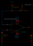
ACanalysis.PNGACresponseof1StageOTA.PNG
From the result you can see, the OTA open loop gain is 76.71dB, UBW is 7.9MHz and open loop PM is (180-126.4)=53.6 degree.

I do not know how to calculate a current integrator loop gain since the input can be any current.
 
Last edited:

For a fast response with no overshoot, Q = 0.5, which corresponds to a 76 degree phase margin. PM of 45 degrees is somewhat oscillatory.

Why would a current integrator be any different than any other closed-loop feedback system? I'm not saying it's not different. Just wondering.
 

PM requirement is calculated with loop gain. For a closed-loop system with a closed loop gain larger than 1, OTA PM requirement is lower, i.e., can be lower than 45 degree. A buffer (closed gain is 1) has the worst situation and requires largest PM.

I do not know how to calculate a current integrator loop gain since the input can be any current.

For a fast response with no overshoot, Q = 0.5, which corresponds to a 76 degree phase margin. PM of 45 degrees is somewhat oscillatory.

Why would a current integrator be any different than any other closed-loop feedback system? I'm not saying it's not different. Just wondering.
 

PM requirement is calculated with loop gain. For a closed-loop system with a closed loop gain larger than 1, OTA PM requirement is lower, i.e., can be lower than 45 degree. A buffer (closed gain is 1) has the worst situation and requires largest PM.
I do not know how to calculate a current integrator loop gain since the input can be any current.

I am not sure if you have an incorrect understanding of PM or if you have expressed yourself not very clear.
The PM requirements do not depend on the desired closed-loop gain. You can ask for PM=45 deg in case of a unity-gain amplifier (buffer) or for a gain-of-100 amplifier.
That means: It is not the buffer application that requires the "largest PM".

Perhaps you mean that the buffer is the most critical application and requires a larger bandwidth - if compared with a higher gain amplifier stage (having the same PM).

Anyway - why don`t you show us the circuit diagram?
 

Here PM I am talking is directly from open-loop OTA ac analysis simulation result; not from loop ac analysis.

I attached the simulation setup and simulation result in my original message to avoid misunderstanding.

I am not sure if you have an incorrect understanding of PM or if you have expressed yourself not very clear.
The PM requirements do not depend on the desired closed-loop gain. You can ask for PM=45 deg in case of a unity-gain amplifier (buffer) or for a gain-of-100 amplifier.
That means: It is not the buffer application that requires the "largest PM".

Perhaps you mean that the buffer is the most critical application and requires a larger bandwidth - if compared with a higher gain amplifier stage (having the same PM).

Anyway - why don`t you show us the circuit diagram?
 

Here PM I am talking is directly from open-loop OTA ac analysis simulation result; not from loop ac analysis.
I attached the simulation setup and simulation result in my original message to avoid misunderstanding.

OK - so you have analyzed the amplifier alone - without any feedback elements.
That means, the measured phase deviation is identical to the loop phase in case of 100% feedback only - and, thus, the difference to 180 deg gives the PM. OK?
 

Right.

I want figure out what is OTA open-loop PM requirement for a current integrator.

What is the output impedance of your active element ? Very high (OTA) or very low (opamp) or something between?
 

I designed two active element: one is OTA (high output impedance and ~100nA drive current ), and the other one is opamp designed with the same OTA followed by a voltage follower stage (low output impedance and ~15uA drive current capability). Does the output impedance affect PM requirement?
What is the output impedance of your active element ? Very high (OTA) or very low (opamp) or something between?
 

Yes, of course.
Any element (R or C) connected to the output influences the open-loop gain of the active device - if it has a large output impedance. And this applies to any feedback element also.
This is because an OTA can be seen as a current source that develops a voltage across a load impedance (in parallel to the internal source impedance).
In contrary, an opamp has a low output impedance and the open-loop gain does not depend on any load.
 
When I run the AC simulation, I already put the feedback capacitor at the active element output as load capacitor. I run the simulation and get the open loop PM from the simulation result.

My question is: what is the open loop PM requirement for a current integrator with a feedback capacitace?


Yes, of course.
Any element (R or C) connected to the output influences the open-loop gain of the active device - if it has a large output impedance. And this applies to any feedback element also.
This is because an OTA can be seen as a current source that develops a voltage across a load impedance (in parallel to the internal source impedance).
In contrary, an opamp has a low output impedance and the open-loop gain does not depend on any load.
 

When we designing transimpendance/charge-sensitive preamplifiers for radiation detectors (also for optical applications but with some different goals), which always work as current integrator we aiming to PM not less than 85 degrees. In addition a stability of that preamplifier depends to feedback loop which is responsible for a dominant pole.

If You want to check a stability of your amplifier, You should make a simulation cell including your amplifier with feedback, all input and output capacitances and to make "stb" analysis (in spectre). For it You only need to insert directly to the input of opamp an element from analogLib→iprobe.
The results You get from ade L → results→direct plot→stability summary.
 
Last edited:
Your reply is very helpful. I will give it a shot. Thank you so much!

When we designing transimpendance/charge-sensitive preamplifiers for radiation detectors (also for optical applications but with some different goals), which always work as current integrator we aiming to PM not less than 85 degrees. In addition a stability of that preamplifier depends to feedback loop which is responsible for a dominant pole.

If You want to check a stability of your amplifier, You should make a simulation cell including your amplifier with feedback, all input and output capacitances and to make "stb" analysis (in spectre). For it You only need to insert directly to the input of opamp an element from analogLib→iprobe.
The results You get from ade L → results→direct plot→stability summary.
 

Hi Dominik,
Can you explain the significance of 85 degrees; I mean as mentioned we will be having all the poles in real axis(no ringing) if we target 76deg; Is there some explanation for 85degree too?
 

Hi yuvan. This 85 degrees is an aim for practical reason. Each layout parasitic could decrease PM for a few degrees, in addition could happens that some physical effects are not modeling or not modelling property and it could decrease a PM for another few degrees (I know a case of a prototype of multichannel front-end for silicon strip detector fabricated in DMILL 0.8 bicmos technology whose ringing but in simulations preamplifier has PM ~75degrees, because models not including some bulk effects). Also its important for multichannel chips together with good PSRR but its a bit longer story ;-)
 
Good comments. Dominik.
Hi yuvan. This 85 degrees is an aim for practical reason. Each layout parasitic could decrease PM for a few degrees, in addition could happens that some physical effects are not modeling or not modelling property and it could decrease a PM for another few degrees (I know a case of a prototype of multichannel front-end for silicon strip detector fabricated in DMILL 0.8 bicmos technology whose ringing but in simulations preamplifier has PM ~75degrees, because models not including some bulk effects). Also its important for multichannel chips together with good PSRR but its a bit longer story ;-)
 

I have one more comment ;-)
In fact whole Body theory is made with silent assumption that we have voltage driven opamp with only resistive feedback so we are able to break a loop and check the phase margin. Of course in this case we don't changing conditions of circuit and whole well known theory works. The problems begins where with have "impendance" feedback or/and we have some other "local" feedbacks and we have amplifier working in other than typical voltage amplifier application modes. In that cases, dependly to method of breaking loop we changing circuit conditions and overestimate or underestimate our stability. Its look like Heisenberg uncertainty principle or a Schroedinger cat problem - each try of checking stability of circuit influenced to circuit.
One of the method to control stability is always to check a transient response of circuit and/or using pole-zero simulations after some hand-made small signal analasys which could help us to understand of pole-zero sims results.
 

..... In that cases, dependly to method of breaking loop we changing circuit conditions and overestimate or underestimate our stability.

Dominik, I cannot agree with you.
In case we break the loop correctly (including bias point restauration and keeping the load conditions at the opening) the classical stability criterion applies - independent on the kind of feedback (with or without frequency dependent components). That means there is no "danger" to over- or underestimate the stability properties. I see absolutely no relation to the uncertainty principle.
 

@LvW. I'm talking about some special cases existed in some application. The best example of this is a frequency analysis of Krummenacher loop. If You check an existed literature You are able to find only a few papers with one quite good analysis but all of authors made some mistakes - the best work was made by one guy from my university (Robert Szczygieł - a paper was from around 2009) but he probably made everything by hand and mistook a zeros locations (if I good remember his analysis). Another example is transimpendance/charge-sensitive amplifier based on source follower buffered regulated cascode design. You feedback loop is made by capacitor with resistor/transistor parallel connection. In addition You need to compensate an amplifier with some capacitors. The most classical solution is to apply miller capacitance between output of cascode (before follower) and input which is driven from high output impendance current source (radiation detector or optical diode, whatever). The second solution is to apply feed-forward compensation on cascode device (look for the Sansen paper from 1990). But In this case in fact you produce a more than one feedback loop. It's very hard to simulate this property.

So summarizing, for most applications a standard theory and simulation methods works good but for some applications we are unable to check stability in such simple and convinced way.

One my friend prepare some presentation about stability analysis of preamplifiers works in transimpendance/charge-sensitive modes (current integration in overall) and when its will be available I will post a link to this.
 
Last edited:

@LvW. I'm talking about some special cases existed in some application. The best example of this is a frequency analysis of Krummenacher loop. If You check an existed literature You are able to find only a few papers with one quite good analysis but all of authors made some mistakes - the best work was made by one guy from my university (Robert Szczygieł - a paper was from around 2009) but he probably made everything by hand and mistook a zeros locations (if I good remember his analysis). Another example is transimpendance/charge-sensitive amplifier based on source follower buffered regulated cascode design. You feedback loop is made by capacitor with resistor/transistor parallel connection. In addition You need to compensate an amplifier with some capacitors. The most classical solution is to apply miller capacitance between output of cascode (before follower) and input which is driven from high output impendance current source (radiation detector or optical diode, whatever). The second solution is to apply feed-forward compensation on cascode device (look for the Sansen paper from 1990). But In this case in fact you produce a more than one feedback loop. It's very hard to simulate this property.

So summarizing, for most applications a standard theory and simulation methods works good but for some applications we are unable to check stability in such simple and convinced way.

One my friend prepare some presentation about stability analysis of preamplifiers works in transimpendance/charge-sensitive modes (current integration in overall) and when its will be available I will post a link to this.

I look forwards to this presentation slides. Plz tell me when you post it out.
 

Status
Not open for further replies.

Part and Inventory Search

Welcome to EDABoard.com

Sponsor

Back
Top