Continue to Site

Welcome to EDAboard.com

Welcome to our site! EDAboard.com is an international Electronics Discussion Forum focused on EDA software, circuits, schematics, books, theory, papers, asic, pld, 8051, DSP, Network, RF, Analog Design, PCB, Service Manuals... and a whole lot more! To participate you need to register. Registration is free. Click here to register now.

Question of calculating impedance in time domain

Status
Not open for further replies.

bhl777

Full Member level 6
Full Member level 6
Joined
Sep 30, 2008
Messages
363
Helped
0
Reputation
0
Reaction score
0
Trophy points
1,296
Visit site
Activity points
5,140
Hi All, I have a circuit like this:
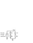
RC.jpg

Different resistors R1 and R2 are connecting with different capacitors C1 and C2 in separately. A periodic triangle wavefomr current is charging the capacitors and resistors, and produce a periodic output voltage.

Currently I am trying to calculate the peak to peak ripple of the output voltage. One way is to use laplace transform to apply in current (I(s)) RC network (Z(s)) to calculate Vout(s)=I(s)*Z(s), then use inverse laplace transform to calculate Vout(t).

However, it is not easily done by hand calculation, and I was trying to use the convolution between "I(t)" and "the inverse laplace transform of Z(s)" to calculate Vout (t). However, what I got from the spreadsheet and SPICE simulation does not match.

I have the following questions:
(1) Is this the correct approach to go, by converting the multiplication is frequency domain to the convolution of time domain?
(2) I have never heard of the impedance in time domain, which is L-1{Z(s)}(inverse L transform), is it the right way to calculate the convolution of I(t) and Z(t) to get Vout(t)
(3) If that is not the right way, which is the best way for hand calculation/EXCEL spreadsheet to implement? It seems like for this case, using the calculation in s-domain and then inverse L transform is only feasible in SPICE but not in hand analysis.

Thank you!
 

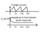
The convolution with inverse Laplace transformed should work. The term impedance is reserved for frequency domain, I think. In time domain, we are talking of pulse response.

I don't see how the calculation can be easily performed in a spreadsheet calculator.
 

This is a different approach from the way you are doing it, but it could yield a result which is useful for sake of comparison.

Pretend the incoming waveform is a sinewave.

R1*C1 presents a certain impedance to the frequency.
Calculated by the formula 1 / ( 2 Pi R C )

R2 * C2 shows a certain impedance to the frequency.

The RC networks are in parallel. Their net effect is a voltage divider, along with the input resistance. It attenuates the input signal.

For a sinewave you can calculate the attenuation.

A triangle wave contains chiefly the fundamental frequency. So I suspect the attenuation is the same with a triangle wave, but I don't know that I can prove it. In fact there would be greater attenuation because the higher overtones in the triangle wave get reduced to a greater degree.
 

The convolution with inverse Laplace transformed should work. The term impedance is reserved for frequency domain, I think. In time domain, we are talking of pulse response.

I don't see how the calculation can be easily performed in a spreadsheet calculator.

- - - Updated - - -

Hi BradtheRad, thanks for your comment. I have a question here, why "The RC networks are in parallel. Their net effect is a voltage divider"?


This is a different approach from the way you are doing it, but it could yield a result which is useful for sake of comparison.

Pretend the incoming waveform is a sinewave.

R1*C1 presents a certain impedance to the frequency.
Calculated by the formula 1 / ( 2 Pi R C )

R2 * C2 shows a certain impedance to the frequency.

The RC networks are in parallel. Their net effect is a voltage divider, along with the input resistance. It attenuates the input signal.

For a sinewave you can calculate the attenuation.

A triangle wave contains chiefly the fundamental frequency. So I suspect the attenuation is the same with a triangle wave, but I don't know that I can prove it. In fact there would be greater attenuation because the higher overtones in the triangle wave get reduced to a greater degree.
 

Attachments

  • CONVOLUTION.png
    CONVOLUTION.png
    14.7 KB · Views: 124
Last edited:

In a practical sense, if both time constants, T1, T2 are greater than the triangle ramp period, then the ripple may be straightforward. V=I*ESR , where ESR = R1//R2. The voltage ripple is regardless of value of capacitor.

With source current suggested as bipolar triangular , this results in triangular voltage ripple.
True indeed. I understood that the OP was asking for an exact solution whyever.
 

Hi BradtheRad, thanks for your comment. I have a question here, why "The RC networks are in parallel. Their net effect is a voltage divider"?

As we know, an RC combination creates an AC voltage divider.

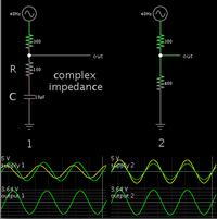
Your schematic has an additional input resistor (or it needs one in order for the problem to make sense). I rearranged the components so the resistors are neighbors. It becomes obvious that we are still dealing with an RC network.


The capacitive reactance is a complex impedance (calculated by drawing a parallelogram).

Anyway with the 100 ohm resistor and 40 Hz sinewave, the overall figure works out to 798 ohms as shown in the right-hand schematic.
 

I must confess that I don't understand why you refer to a voltage divider to calculate the impedance of a RC series-parallal circuit. In any case, knowing the impedance for specific frequencies doesn't give the time domain solution for waveforms with harmonic components.
 
  • Like
Reactions: LvW

    LvW

    Points: 2
    Helpful Answer Positive Rating
Status
Not open for further replies.

Part and Inventory Search

Welcome to EDABoard.com

Sponsor

Back
Top