Continue to Site

Welcome to EDAboard.com

Welcome to our site! EDAboard.com is an international Electronics Discussion Forum focused on EDA software, circuits, schematics, books, theory, papers, asic, pld, 8051, DSP, Network, RF, Analog Design, PCB, Service Manuals... and a whole lot more! To participate you need to register. Registration is free. Click here to register now.

question : Design of buck converter for high slew rate load transient conditions

Status
Not open for further replies.

cmos_ajay

Full Member level 2
Joined
Jan 30, 2007
Messages
126
Helped
0
Reputation
0
Reaction score
0
Trophy points
1,296
Activity points
2,247
Hello,
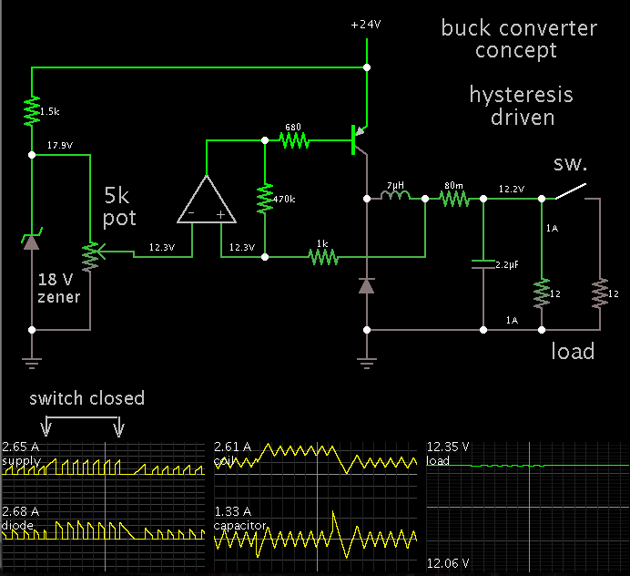
I need to design a fast slew rate , load transient response Step-down power converter. The load is a microprocessor used in desktop application. Does someone know how to select the inductor L and capacitor value ?
How do we determine the number of capacitors in parallel based on transient response conditions ?

I had read one paper called Optimal output filter design for microprocessor or DSP power supply...........but its difficult to understand. Does anyone have a better approach ?

Regards.
 

A few things are key:
1. Very low ESR capacitors
2. Low inductance values
3. High switching frequency
4. Current mode control

I've also read in some white papers that valley current mode control has faster transient response than peak CMC for buck converters with low duty cycles.
 

Does someone know how to select the inductor L and capacitor value ?

A large smoothing capacitor will slow down any change in output voltage. Therefore it should be no larger than will keep ripple within a tolerable range for your equipment.

To bring up some ballpark estimates...

Suppose you aim for a frequency of 1 MHz. And suppose you need 1A at 12V.

Then a coil value in the 1-10 uH range should be suitable. And a smoothing capacitor between 1uF and 10 uF.
 

Another way is to use a multiphase buck converter.

Intersil has a wide portfolio of controllers, specifically designed for use with high end microprocessors.
 

If you insist to switch at 1MHz then your loop bandwidth (aside from
schemes like hysteretic) will be quite a bit lower and way, way more
slow than a fast digital part's load-step can be. In this case you have
to depend on the output filter to hang tough until the loop comes
around to help out. A light filter may be more agile but this helps none
if you've dropped the output voltage below limits already.

I think getting to an agreed-adequate load step response requirement
against an agreed-worst-case step (current and risetime, and do not
neglect the max-to-min counterpart where loop response is likely the
worst for overshoot) is the start of this journey. Or you can cut-and-try
your way to what you think looks best, but it's always nice to know
just what the ball looks like before you pick your shoes.
 

If you insist to switch at 1MHz then your loop bandwidth (aside from
schemes like hysteretic) will be quite a bit lower and way, way more
slow than a fast digital part's load-step can be.
1MHz if often sufficient for midrange microprocessors and FPGAs. It's only when you get into desktop CPUs that you start needing multi-MHz interleaved converters.

But it the end, it takes a fair bit of analysis (or a ton of simulation) to predict the response of a converter's output.
 

Speaking of a ton of simulation...

This one illustrates (theoretically) how a hysteresis-driven buck converter might respond to a sudden change in load.

Frequency and duty cycle are controlled by hysteresis response, based partly on current through the coil, and partly on a reference voltage adjusted at the left.

By closing the switch, the load is doubled. Response is immediate. Duty cycle is lengthened so greater current can build in the coil. Operation stabilizes within a cycle or two.

Response is similar when the extra load is removed. Again operation stabilizes in a cycle or two.

Regulation stays within a few percent.

As for what tightness of regulation your equipment requires, I suppose you'll have to find out by experimentation.


Hello, I have a picture of a hysteritic controller based dc-dc converter. Does anyone have a simple SPICE model for it in say LTSPICE ? It will be helpful to test and get a feel for the transient response.
Thanks.
 

Attachments

  • hysteretic control.jpg
    hysteretic control.jpg
    97.8 KB · Views: 89

It looks as though your sense wire is located in a less sensitive position. It responds to volt level as it is filtered by the smoothing capacitor. Hysteresis will be 'loose'. This defeats your specification of fastest possible response to a load change.

The solution is to put the capacitor immediately next to the load. Then your sense resistor will be more sensitive to each cycle of current through the coil.

At 1.65V output voltage, I suppose your ampere draw is much less than I guessed. So I toned it down to 50 mA, and am trying a new simulation.

With a coil value .14 uH, your frequency is in the 50 to 150 MHz range. Waveforms will look similar to my post #7 schematic.

I am not using LTSpice, but there is no reason you cannot. It gets mentioned favorably often at this board, and it contains several IC's you might find useful to constructing this project.
 

Hello, I have a picture of a hysteritic controller based dc-dc converter. Does anyone have a simple SPICE model for it in say LTSPICE ? It will be helpful to test and get a feel for the transient response.
Thanks.
A working model could easily be built in LTspice from very basic components (dependent voltage sources, voltage controlled switches, etc). Delay in the feedback should also be accounted for, within reasonable limits (tens of nanoseconds at least).

Also if you use such a low choke inductance, then you can expect the ESL of your output capacitor to play a significant role as well...
 

Status
Not open for further replies.

Similar threads

Part and Inventory Search

Welcome to EDABoard.com

Sponsor

Back
Top