Continue to Site
Follow along with the video below to see how to install our site as a web app on your home screen.
Note: This feature may not be available in some browsers.
I'm curious: What's the context of the picture? Is it an actual implementation, or is it some kind of model for a simulator?
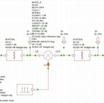
Think of the attenuators as providing isolation between the devices (in both directions). The one to the left of the mixer provides a slightly better match of the mixer's input (2 additional dB of RL) to components to the left of the mixer. But it also provides a better match for the mixer looking back (left) into those same components. Same on the output of the mixer.
So the mixer's output attenuator can appear to improve the S11 of the filter (especially for its out-of-band regions) that's to the right of the mixer (which is part of what Dan was pointing out I believe), making the mixer "happier".
I asked if it was for a simulation because often times the models for devices do not have a good enough representation of the real world so sprinkling attenuators around can help with the simulations. But sometimes the attenuators are also appropriate in a real design.