Continue to Site

Welcome to EDAboard.com

Welcome to our site! EDAboard.com is an international Electronics Discussion Forum focused on EDA software, circuits, schematics, books, theory, papers, asic, pld, 8051, DSP, Network, RF, Analog Design, PCB, Service Manuals... and a whole lot more! To participate you need to register. Registration is free. Click here to register now.

Question about super capacitor for RTC backup

Status
Not open for further replies.

zenniz

Junior Member level 3
Joined
Mar 25, 2013
Messages
29
Helped
0
Reputation
0
Reaction score
0
Trophy points
1,281
Location
Singapore
Visit site
Activity points
1,497
I am intending to use super capacitor as a backup for my micro-controller's RTC.
My micro-controller is powered by a 5V, 2.5A power supply and the RTC backup consumed 30uA without the power supply.

I have never dealt with a super capacitor for backup so here is my doubt.
I did some research on super capacitor, many have a voltage rating of 5.5V.

It is possible to charge the 5.5V super capacitor with my 5V power supply?

and

It is safe to charge a super capacitor with a voltage rating below 5V with my 5V power supply???

and

What is the best capacitance rating for my set up if there is a power failure that will last for 12 hours?
 

RTCs usually are designed to work down to 3 v or less, if powered from their Vb pin, which usually is different from the Vdd pin.......but of course, without actually knowing which IC you are using, this is only a guess.
 

30 µA is obviously referring to a µC with built-in RTC because no dedicated RTC chip has a that high current consumption. They rarely have a separate RTC power supply. If the processor runs from 5V, a 5.5V supercap can be a simple option to implement a backup supply. I personally think that 12 hours backup is unconveniently short and won't correspond to user's expectations.
 
  • Like
Reactions: tpetar

    tpetar

    Points: 2
    Helpful Answer Positive Rating
Just to give an idea - I'm working on a project right now that uses a 0.47F 5.5V capacitor to keep a DS1302 RTC running from a 3.3V supply and using the DS1302 internal charge circuit. The clock is still running in test after about 1 month with all power supplies shut down. I would guess it would still run for another month or so before it discharges enough to stop the clock running. I've also used 18F46J11 PICs which have an internal RTC but found them quite difficult to keep running for long periods due to higher current consumption.

Brian.
 
  • Like
Reactions: FvM

    FvM

    Points: 2
    Helpful Answer Positive Rating
What is Vcc min for the RTC? 1.5? 2.5V? ??

If the Cap is charged to say 4.5V worst case. and Vcc min is say 2.5V then a 2V drop is the difference.

estimate C min using Ic=C dV/dt with Ic=50uA, dV=2V, dt=12hrs*3600=43200s
then Cmin= 50e-6 *43200 / 2 = 1.08F
 
  • Like
Reactions: zenniz

    zenniz

    Points: 2
    Helpful Answer Positive Rating
Vcc min is 1.8V

Thanks for the formula, it helps alot.
 
Last edited:

Don't confuse the voltage rating of the capacitor with the actual voltage across it. A higher voltage rating will do no harm, it simply means you have a higher safety margin above the voltage you are acually using but an actual higher voltage may damage your RTC. Also, beware of residual charge when first connecting a 'super' capacitor. They hold their charge for months if nothing drains them so if it has been used in a different circuit, make sure it isn't still charged up before connecting it.

Brian.
 

RE: Betwixt

i'm using NXP LPC1768 mbed micro-controller (Link provided below)
https://mbed.org/handbook/mbed-NXP-LPC1768


Assuming that i'm using a 5.5V 1f rating super capacitor and it is connected to the micro-controller Vb pin (RTC backup pin)
My micro-controller Vb pin is rated at 3.3V - 1.8V
My power supply is supplying 5V to both my microcontroller Vin pin (power pin) and the super capacitor.

Will the voltage of the super capacitor that is charged to 5V damage my Vb pin?
Should i add a 3.3V voltage regulator to charge the super capacitor so that it is within the micro-controller Vb pin's rating?
 
Last edited:

The question would be much easier to answer if you mention the processor type. But it sounds like you must not supply more than 3.3V to Vb.
 

The details of the mbed board are sketchy but if I understand it, you should connect the 3.3V OUTPUT from the board through a current limiting resistor and blocking diode to the Vb pin and add the capacitor from Vb to ground. In other words use the on-board regulator to provide 3.3V to charge the capacitor. If you use a small Schottky diode (suggest BAT85) you will only lose say 0.3V so the cap should charge to around 3V without danger of it discharging anywhere except the Vb pin. I would not recommend using a higher capacitor voltage then a regulator to drop it to 3.3V, the regulator will itself draw far too much current and reduce the backup time considerably.

Brian.
 
  • Like
Reactions: zenniz

    zenniz

    Points: 2
    Helpful Answer Positive Rating
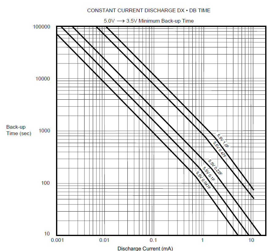
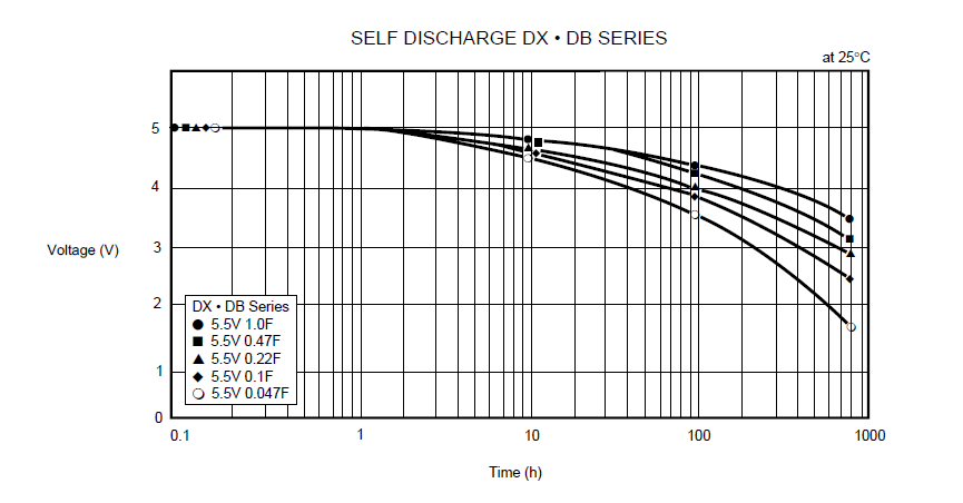
I'm just going to leave this here
3495291600_1367316140.png

1087751600_1367316291.png
 

Attachments

  • Double Layer Capacitor.pdf
    202.5 KB · Views: 186
  • Like
Reactions: zenniz

    zenniz

    Points: 2
    Helpful Answer Positive Rating
Hi all,

I am quite new to the super cap. My application was to use the super cap to power up the microcontroller (PIC18f46k20) while there is a power failure from main power supply.
My question is how to calculate and estimate the duration of my super cap can last before the micro controller turned off.
voltage full charge (super cap) = 3.3V
voltage min working (super cap) = 1.8V
C = 3.6V 10F
As the Vcc drop , I consumption of microcontroller will drop also. What is the best method to calculate the duration? Thank you very much
 

You should really start a new thread for your question but the answer is: it depends more upon what other circuitry is being driven than what the processor itself uses. Most current from a processor is flowing in and out of it's IO pins and any outgoing current has to come from the supply and therefore the backup capacitor. If you can put the processor to deep sleep mode, it should last for a few days but of course it can't do anything during that time. If left running, it may only last a few minutes depending on your design.

Brian.
 

Hi betwixt,
I already configured my MCU into low power mode and an external oscillator was connected to my MCU timer1 to wake up my MCU every 1 min. I disconnect and turned off all my peripheral device.

During sleep mode and Vcc = 3.3V, the current consumption of my MCU is 0.1~3uA.
During active mode and Vcc = 3.3V, the current consumption of my MCU is 5~10uA.
If i replace the power supply with my full charge capacitor, the voltage may drop and the current consume will change accordingly. Thus i can't figure out how to calculate the duration taken for the Vcap drop from 3.3v to 1.8v.

I already setup a test device since last Wednesday. My Full charge super cap voltage(3.3V) take seven days to drop to (2.56v). I need a formula which allow me to calculate the duration of V cap drop from 3.3v to 1.8V.
 

I'm using a mobile phone so entering math formulae is difficult!

Assume the current stays contant as the voltage drops, that won't be far from correct. Look at this page: https://en.wikipedia.org/wiki/RC_time_constant you can work out R using the voltage and current you know already.

Brian.
 

Hi Betwixt,

Thank you very much. So according to your reply, i may need to use a power supply to connect it to my microcontroller and measure the current consumption vs voltage drop. From there, i can calculate the impedance of MCU by using V = IR. Am i right ?
Since the R is a known value, i can just use the capacitor discharge formular to calculate the time taken. V=Voe^-(t/CR). Please advise me if my concept is incorrect. Thank you
 

That's correct. You could use a variable PSU to check the consumption at several voltages between 3.3V and 1.8V but you might find variation from one processor to another makes as much difference as the voltage. I'm not familiar with that processor but if it has an on-board voltage regulator you might find the V/I is not linear as the regulator circuits compensate for the voltage dropping. Even if you assume the worst case current is drawn all the time and then use the discharge formula, it will give a minimum life expectancy and any less current will be a bonus.

Brian.
 

I once measured microcontroller current consumption very thoroughly. I've studied Atmel and Microchip controllers, but would think that my observations below apply to most other brands:

1) A microcontroller's current consumption IS NOT constant. It varies all the time, sometimes an order of magnitude or more. You need to take several reading over -let's say- 1 minute period and then average them.
2) You'll find that the current consumption varies as the controller enables the ADC ports, turns on and off the different outputs, or reads/writes on any external bus (I2C, SPI, RS232).
3) It goes without saying that different clock speeds DRAMATICALLY change consumption.
4) There are other features, like brown out detection or timers that have an impact also.
5) When one is squeezing the last microamp, even trivial things live leaving input pins floating increase current. If you have unused inputs, either use a pulldown resistor or, if the architecture allows it, make the port an output and set it low.
6) Most datasheets discuss strategies to reduce current. Study those.

EDIT: After re-reading your post above, I realized that you are using a pre-built module and some of my advice is not applicable in this case. I'm leaving the message however, since the recommendations may be useful to other readers.
 
Last edited:

Status
Not open for further replies.

Similar threads

Part and Inventory Search

Welcome to EDABoard.com

Sponsor

Back
Top