Continue to Site

Welcome to EDAboard.com

Welcome to our site! EDAboard.com is an international Electronics Discussion Forum focused on EDA software, circuits, schematics, books, theory, papers, asic, pld, 8051, DSP, Network, RF, Analog Design, PCB, Service Manuals... and a whole lot more! To participate you need to register. Registration is free. Click here to register now.

Question about NMOS switch linearity spectrum

Status
Not open for further replies.

shico90

Junior Member level 2
Joined
Apr 7, 2011
Messages
23
Helped
0
Reputation
0
Reaction score
0
Trophy points
1,281
Activity points
1,418
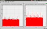
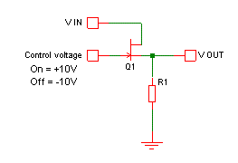
Hello, I'm testing the NMOS transistor as a switch to see its linearity and I got the following spectrum. on the left the spectrum of the input and on the right the spectrum of the output. the harmonics of the output is very large. Is that normal for the linearity of the NMOS transistor or there is something wrong in the simulation?
 

Attachments

  • Screenshot at 2012-04-30 18:32:02.png
    Screenshot at 2012-04-30 18:32:02.png
    39 KB · Views: 59
  • Screenshot at 2012-04-30 18:16:37.png
    Screenshot at 2012-04-30 18:16:37.png
    31.9 KB · Views: 56

Re: nmos switch linearty

First, are you sure you're running this in the linear region? If not, you may just be seeing distortion. Have you looked at your input/output in the time domain?
 

Re: nmos switch linearty

I'm a little confused by the circuit. There seem to be two inputs; a square wave and a sine wave. I also don't see a DC path between source and drain, or any DC power source.

What is the circuit supposed to do? Where is the output?
 

Re: nmos switch linearty

I'm a little confused by the circuit. There seem to be two inputs; a square wave and a sine wave. I also don't see a DC path between source and drain, or any DC power source.

What is the circuit supposed to do? Where is the output?

Oh, yeah, that's a good point! I didn't even look at the circuit! I was just making a global comment.
 

Re: nmos switch linearty

On second thoughts, I guess it's being used to switch a signal, as in the JFET version below. It does need a load impedance on the output though.

To check linearity it should be tested with the switch either on or off. Looking at the spectrum while it is switching is no good, since the signal is being chopped up and some of the switching waveform will leak to the output too.


Status
Not open for further replies.

Part and Inventory Search

Welcome to EDABoard.com

Sponsor

Back
Top