Continue to Site

Welcome to EDAboard.com

Welcome to our site! EDAboard.com is an international Electronics Discussion Forum focused on EDA software, circuits, schematics, books, theory, papers, asic, pld, 8051, DSP, Network, RF, Analog Design, PCB, Service Manuals... and a whole lot more! To participate you need to register. Registration is free. Click here to register now.

Question about board level connection of a BJT, with external bias current source

Status
Not open for further replies.

bhl777

Full Member level 6
Joined
Sep 30, 2008
Messages
363
Helped
0
Reputation
0
Reaction score
0
Trophy points
1,296
Activity points
5,140
Hi, I have one fabricated BJT device (not power BJT) and want to use an external uA current to bias it. However, I have some questions about the board level connecting, and would anybody advise me about the four questions in the picture? Thank you!
bjt connection.jpg
 

Without knowing the EMI immunity of the layout, you must consider the breakdown voltages for each terminal to protect it from excess reverse voltage One diode could be used for this purpose especially with inductive lines and open circuit with current. Keep the Current loop small in area with coax or twisted pair and you may still need a CM choke.

Beware of ESD damage and use whatever protection diodes, TVS etc to protect the device leads and capacitive discharge on connections.
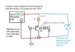

Thank you SunnySkyguy! I revised the connection scheme, and would you answer my questions in the picture? Thank you!
bjt connection2.jpg
 

I revised the connection scheme, and would you answer my questions in the picture?
View attachment 120371

I think you shouldn't leave the pnp's bulk floating. Better connect it to the most positive potential, together with the 2V Zener's cathode. Or - if this isn't possible - to the emitter.

A 2V-Zener will have a non-negligible leakage current. Measure it and adjust your current source.
 
  • Like
Reactions: bhl777

    bhl777

    Points: 2
    Helpful Answer Positive Rating
Status
Not open for further replies.

Part and Inventory Search

Welcome to EDABoard.com

Sponsor

Back
Top