Continue to Site

Welcome to EDAboard.com

Welcome to our site! EDAboard.com is an international Electronics Discussion Forum focused on EDA software, circuits, schematics, books, theory, papers, asic, pld, 8051, DSP, Network, RF, Analog Design, PCB, Service Manuals... and a whole lot more! To participate you need to register. Registration is free. Click here to register now.

[SOLVED] query about uln2803a

Status
Not open for further replies.

vishu489

Advanced Member level 4
Full Member level 1
Joined
Aug 28, 2011
Messages
116
Helped
3
Reputation
6
Reaction score
3
Trophy points
1,298
Activity points
2,120
hey Friends , currently I'm referring uln2803a data book . from datasheet i know the following points

1. device can sink current up to 500ma
2. we need to add pull up resistor to each o/p for which we can pull up to 50v.
3. we can give i/p voltage max up to 30v
4.for inductive load we have to connect com terminal to inductive load supply voltage to avoid back emf effect

now i just wanna know that am i correct or not ?
 

1. Rightooo, each driver output can sink up to 500mA, but watch out for total power dissipation and temperature rise.
2. Right..., resistor, LED, coil, load, must ,of course, have the high rail connected and this part switches the low side.
3. Right..., 30V input ..can see some application for that:)
4. Right..., nice feature, but for relays with negative clamping deenergizing circuit this freewheel diode "shorts" fancy circuit and extends relay deenergize time. Also, used this for a LAMP TEST function when using this to drive lamp panels.
 

device can sink current up to 500ma

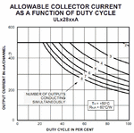
This graph shows the max current per output depending on the simultaneous outputs conducting
ULN2803_output.GIF
 

sorry for late reply . alex but i'm not able to interpret that graph properly. will you please explain it?
 

Hi,

The diagram is saying how much current each channel can deliver depending on how it is driven.

Example, if you have all eight inputs fully on the 8 outputs can only deliver about 180ma each.


Rather than going over the details of the chip it might be easier if you say what your input signals are and what your output devices/ loads are going to be.

Given all that, in the real world its good practice not to drive any device to its maximum or your can expect early failure /excessive heat.
I typically derate all power components by at least 30%.
 
Status
Not open for further replies.

Similar threads

Part and Inventory Search

Welcome to EDABoard.com

Sponsor

Back
Top