rightx2
Newbie level 4

- Joined
- Nov 6, 2013
- Messages
- 6
- Helped
- 0
- Reputation
- 0
- Reaction score
- 0
- Trophy points
- 1
- Activity points
- 54
HI. I want to know how to choose suitable resistors(value) around transistor.
this contents is from Electronics all in one for Dummies.
Please refer the attached file, and answer the question.
Contents in Book
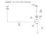
- R1: 330ohm resistor limits the current through the LED to prevent the LED burning out. You can use Ohm's law to calculate the amount of current that the resistor will allow to flow. Because the supply vol is 6v, and the LED drops 1.8v, the voltage across R1 will be 4.2v (6-1.8). Dividing the voltage by the resistance gives you the current in amperes, 0.127A
- R2 : You can use Ohm's law to calculate the current at the base. Because the base-emitter junction drops about 0.7v, the voltage across R2 is 5.3v
Question 1 : I don't know how to use Ohm's law when there is transister in schmatic. In the Contents, "Because the supply vol is 6v, and the LED drops 1.8v, the voltage across R1 will be 4.2v (6-1.8)." this means it will ignore transistor's inner resistors when using Ohm's law? or it uses Ohm's law from voltage source(+6v) to point "a"??
Question 2 : "Because the base-emitter junction drops about 0.7v, the voltage across R2 is 5.3v" -> how could i know base-emitter junction drops is about 0.7v?? i experiment with various resistors, and this junction drops seems to change every time. Or could i know this in transistor's data sheet?(if it is, could you let me know where can i find it?? i attach the datasheet. please refer sentence(or paragraph) indicating this.)
Question 3 The calculating(Ohm's law) will be different if i put R3 under the point "c"?? i mean R3 between point "c" and ground. How it will change?? please let me know ...
Question 4 : How can i choose certain resistor's value like 330 Ohm, 1K in this picture?? is it just intuition??? or simulate with Circuit Simulate Software before?? I don't know which resistor i have to use when using transistors.
I stuck in depreesion because of this. I can not go further cuz i can't understand how to use and apply transistor T-T... Please Help me !

