Continue to Site

Welcome to EDAboard.com

Welcome to our site! EDAboard.com is an international Electronics Discussion Forum focused on EDA software, circuits, schematics, books, theory, papers, asic, pld, 8051, DSP, Network, RF, Analog Design, PCB, Service Manuals... and a whole lot more! To participate you need to register. Registration is free. Click here to register now.

PWM with BJT driving DC Fan

Status
Not open for further replies.

kikikrunch

Newbie level 4
Newbie level 4
Joined
Sep 2, 2013
Messages
6
Helped
0
Reputation
0
Reaction score
0
Trophy points
1
Visit site
Activity points
42
Capture.JPG

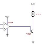
Hi, I would like to enquire on the following circuit. Something which I don't understand about the BJT. The circuit op amp is a PWM output.

I understand that if I put a resistor Rb, it will control the amount of current provided to the DC Fan. However, if I didn't put a resistor Rb, the circuit works too. What I don't understand is that, is it necessary to put a resistor Rb when working with PWM output?

Some specifications

PWM output range 5.5V to 8V
DC Fan maximum 12V @ 0.16A
 

The width of the pulses in the PWM controls the amount of average current in the fan. But the BC108 is very old and had a maximum allowed collector current of only 100mA. Do you have a tiny fan?

What is Rb? A series base resistor? Its current should be 1/10th to 1/20th the collector current. With a +12V supply the datasheet of the LM358 shows that its typical output with with a 10mA load is +10.5V.
The datasheet shows that the typical output high current is 40mA so it is best to use Rb.

Hello! Thanks for your reply. Rb is the series base resistor connected between Vb and BJT. Nope, I'm actually using a computer DC Fan, those 12V, 120mm kind.

Since my working voltage ranges from 5.5v to 8v but it could go to 12V(Input voltage) - 1V(Non-ideal op amp) = 11v maximum, is it right to say that I should use a 27500 Ohm Rb resistor to limit the current(Ib) to 0.4mA since my DC Gain is characterized to be 250?
 

Since my working voltage ranges from 5.5v to 8v but it could go to 12V(Input voltage) - 1V(Non-ideal op amp) = 11v maximum, is it right to say that I should use a 27500 Ohm Rb resistor to limit the current(Ib) to 0.4mA since my DC Gain is characterized to be 250?
Absolutely not!
The hFE (DC current gain) of a transistor is when it is a linear amplifier with plenty of collector to emitter voltage. Not when it is a saturated switch that has a collector to emitter voltage of 0.05V to 0.2V. The saturation voltage loss between the collector and emitter of a transistor is listed when its base current is 1/10th its collector current regardless of its hFE.

If the supply is 12V, the maximum output of an LM358 opamp is 10.5V (but it could be a little less) and the base-emitter voltage of the transistor is 0.8V (but it could be a little more) then if the motor draws 100mA then the base current should be 10mA so the base resistor value is (10.5V - 0.8V)/10mA= 970 ohms. Use 1k ohms.

We still do not know how much current is drawn by your fan.
 
Last edited:
icic...just wondering, where do you get the info of 1/10th of collector current when the switch is not saturated. Because what I've come across is only using the formula of Beta*Ib = Ic
 

icic...just wondering, where do you get the info of 1/10th of collector current when the switch is not saturated. Because what I've come across is only using the formula of Beta*Ib = Ic
The 1/10th value is for a saturated switch, not when it is not saturated.
 

icic...just wondering, where do you get the info of 1/10th of collector current when the switch is not saturated?
A transistor used as a switch is ALWAYS saturated so that the collector to emitter voltage is very low. The datasheets show the saturation voltage loss (Vce) when the base current is 1/10th the collector current.

Beta is used when the transistor is a linear amplifier with plenty of collector to emitter voltage. Frequently the datasheets show the beta when the collector to emitter voltage is 10V.
 

Hmm...the 1/10th collector current is derived from the red box shown below?

fd4vwi.jpg


A transistor used as a switch is ALWAYS saturated so that the collector to emitter voltage is very low. The datasheets show the saturation voltage loss (Vce) when the base current is 1/10th the collector current.

Beta is used when the transistor is a linear amplifier with plenty of collector to emitter voltage. Frequently the datasheets show the beta when the collector to emitter voltage is 10V.
 

Hmm...the 1/10th collector current is derived from the red box shown below?
Yes, but you found a very old BC108 transistor that I used in my first job 48 years ago. It had a low maximum allowed current.
A more modern higher current transistor like the 2N3904 has the 1/10th spec:
 

Attachments

  • 2N3904 saturation spec.png
    2N3904 saturation spec.png
    14.7 KB · Views: 155

Status
Not open for further replies.

Similar threads

Part and Inventory Search

Welcome to EDABoard.com

Sponsor

Back
Top