Continue to Site

Welcome to EDAboard.com

Welcome to our site! EDAboard.com is an international Electronics Discussion Forum focused on EDA software, circuits, schematics, books, theory, papers, asic, pld, 8051, DSP, Network, RF, Analog Design, PCB, Service Manuals... and a whole lot more! To participate you need to register. Registration is free. Click here to register now.

PWM help for Pool lamp...

Status
Not open for further replies.

aq_mishu

Full Member level 4
Joined
Jul 16, 2007
Messages
212
Helped
1
Reputation
2
Reaction score
1
Trophy points
1,298
Activity points
3,402
guys,
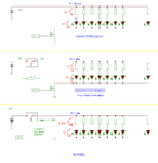
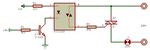
I named this topic PWM because I'm focused on it... but above all, I need a solution. The thing is my authority made the cabling system for AC220, but bought DC3V 350mA LED for their pool lamp. Now I tried with individual rectifier method for each... but the most big prob is space issue while installing. Thus I came with the solution as follows:
Sending Pulsating DC at 5V @ 100Hz. (the cable is within 100ft, with parallel loads of LEDs). This case, I need to give series resistors and the values are real tricky and not available... so suggest me in this case... I mean pulsating DC at 5V/12V with proper freq and resistor value, which is standard value ofcourse.

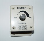
The second method I was thinking was same, pulsating DC, but with PWM (Phase correct) with for 12V, pwm value of 10 (i tried with duty cycle 25% but just burned down a light) or 5V with PWM of 20.

Well, it's best if I can avoid the series resistor and can push the current to lit the LEDs up (amber, high intensity) at 100FT.

Also for PWM, I found LEDs getting hot. should I change the prescale to reduce the frequency??

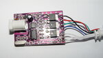
I'm using ATMega8 with 12MHz. And also IRFZ44N for driving.

Guys, I need help...

Mishu~
 

In this case, with parallel loads of LEDs, you need to use some series resistors anyway, in order to compensate the cable resistivity. One idea is to place any value you can find for the series resistor (0.5 ohm to 3.9 ohm), and to use a variable step-down converter (from 5-12V to 3.5-4V). You may later adjust the voltage to obtain the nominal current for each LED.
 

You can find some cheap constant current psu for leds that can be connected to 85-265v AC, in Chinese eshops (and ebay too) they have a price of about $3 US but you can probably find cheaper if you buy a dozen.
This solution would require one driver per led (or 5-6 in series but bot in parallel) and 220v to the supply cable.

I assume you can do it with PWM, you need one resistor for each led so that they share the current equally and also a feedback system controlling the output current to regulate it using PWM so that it stays constant.
So for example if you have 20 leds 20*0.35A=7.5A you should set the mcu to regulate the output current to 7.5A , then with a small resistor in each led you should make sure that all leds share this equally.
An additional advantage would be that the leds couls also be adjusted since you can regulate the current to a lower level to lower the light intensity.

Alex
 

dear alexan_e,
thanks for the ideas... the first thing is I could use standalone led drivers for each, but that's not possible. because of space issue. also from china, i already have a psu for this, which conencts them in series of 10 and it also requires lot of recabling and cutting through walls and tiles for the entire installation. also it has probs, like if one goes out, the whole goes out.

I liked the pwm method you described, generating say .1mA each and 10 LED means 1A total... then I need to add a small resistor (like 1ohm??) with each and the feed the pwm current to 1A?? also I need to sense the current going out from the MosFET right?? so that I can reduce or increase to make it stable 1A?? using PWM ofcourse... and if this, then is it like a automatic constant current regulator with the current of SUM of all LEDs?? (because another part is same intensity for all, but a bit lower intensity than stated in body, to increase lifetime)

In this case, what I really need to do?? Read from a Shunt through ADC and then change the waveform duty cycle according to that to stabilize it?? Just the way we set PWM using a POT??(there it was voltage driven)... and no way except a series resistor??

also can I use 100HZ pulsating sq wave 12V DC to do the power transmission like 50Hz sine?? and then just adding a series resistor of appropriate value for current limiting (the way we do for the pilot lamp of a psu, 500ohm 1/4 watt for a 12v)??? because that i am lanning to use as a backup...

ideas guys...

Mishu~
 

I was mainly talking for a 1 driver per led , small 300mA drivers with 220v power supply, these are quite small but I don't know how small you need
350mA_constant.gif

The PWM I meant was for all leds in parallel with one resistor each (1 ohm should work or maybe lower), something like the buck (step down) converter using a diode/inductor/capacitor to get a steady DC output
kd1jv.qrpradio.com/tiny13switcher.pdf

I have only done something similar for one led using the ADC and then changed the PWM duty to keep the output current constant, the PWM frequency was 20KHz and I was using an AVR mcu
A shunt resistor can measure the current and provide the feedback to the ADC.

also can I use 100HZ pulsating sq wave 12V DC to do the power transmission like 50Hz sine?? and then just adding a series resistor of appropriate value for current limiting (the way we do for the pilot lamp of a psu, 500ohm 1/4 watt for a 12v)??? because that i am lanning to use as a backup...

I don't know what you mean exactly , you want to use a power supply with a pulse wave output and then limit the current by resistors?

Alex
 

The PWM control method will reduce the light intensity by modulating the pulse at a certain frequency. In this case we assumed a maximum intensity to be obtained at the maximum duty cycle, which means all voltage to be applied LED+resistor pair. If we use a high value for the power supply we need also a large resistor to limit the necessary current, and this means we increase power losses in the resistors.


The LED parameters:3V/0.35A.
We suppose to use for a maximum 0.3A. Useful power for one LED = 0.9W
Let’s see what are the implications of the voltage supply to be used for.

Example 1.
Power Supply = 12V
series resistance needed R = 9/0.3 = 30 ohms
Power Loss Due to Resistance P = 9 * 0.3 = 2.7W

Example 2
Power Supply =5V
series resistance needed R= 2/0.3 = 6.67 ohm
Power Loss Due to Resistance P = 0.3 * 2 = 0.6W

Example 3.
Power Supply =3.3V
series resistance needed R = 0.3/0.3 = 1ohm
Power Loss Due to Resistance P= 0.3 * 0.3 = 0.09W


PWM method not applicable if you use a high value for the power supply and a low series resistor (in order to minimize losses), because we’ll obtain a maximum equivalent light intensity only by exceeding the maximum permitted LEDs current .

That’s the idea to use a variable step-down converter (from 5-12V to 3.5-4V)and to adjust the voltage in order to obtain the nominal current for each LED.
 

Attachments

  • PWM.GIF
    PWM.GIF
    29.2 KB · Views: 148
  • Like
Reactions: js

    js

    Points: 2
    Helpful Answer Positive Rating
I don't know what you mean exactly , you want to use a power supply with a pulse wave output and then limit the current by resistors?

Alex

basically, the existing wiring is for AC220v. now with the existing cabling, If I put 5VDC, it will not bring bless to me as the cabling is 100ft long. but if i give AC, then it will carry easily... and thus i was thinking to make an AC, with a much high freq, in a form of square wave... amplitude can be 5v (i'd like to be if it was 3v)

this is one big reason I hate LED for lighting... it requires per led series resistors eitherway... and that value is always a critical one... I could drive the led for 1ohm... but still, that little DC volt first i have to apply over the power bus (that 100ft cable)...

Mishu~

---------- Post added at 01:11 ---------- Previous post was at 01:07 ----------

also, I once made a small rectifier with a small bridge, a 100uF, and a 470ohm 1/2 watt and driven it with 12V to run the led. plan was per led, one rectifier. but again, mounting that rectifier is a hard thing there... because it requires to be mounted into a stair's step, and the light requires to have a hole of 4inch dia for it's own...
 

The advantage of AC over DC is obvious for power transmission lines when it can be changed in voltage using transformers, but using 5VDC or 5VAC in this case doesn’t help to much, same resistive losses in the transmission wires.

The series resistor it’s not critical if you can adapt the power supply to the values used for, in order to get the nominal current of LEDs.
 

previously we tried with 12VAC-sin with individual rectifiers. used a 470ohm 1W resistor. now firstly planning the same, 12VAC with 100ohm 1W. Spot rectifier. Also as I was looking for a dimming effect for turning on, I am also planning to use the PWM after the transformer just to through the AC volt.

Means::

220VAC-Sin-->12VAC-sin-->PWM for dimming(0-100% gradually)-->REctifier per LED with 100ohm 1W


Hope this will work... and other method is just avoiding the rectifier adding the same 100ohm 1W with square wave (which will remove the diode, capacitor)

I'm also planning to try with 5V in this case...

mishu~
 

Using 100 ohms resistors at 12V, the LEDs current = 90mA, is this enough?
 

previously I trued with 470ohm 1W. The boss was not happy with the intensity. Thus choosen 100ohm 1W. Let's see if he satisfies... because 470 was with 12v and when the technician added 24v, with 470, they were happy...

I was thinking of PWM... but now thinking of adding a rectifier and a resistor... as i have to use sine wave 50Hz at 12V for transmission. Plan is local rectifier with limit resistor. PWM i'll use at the AC part just for dimming. I mean soft start... thus it will glow... so the plan is now following...

220VAC--->12VAC---->PWM dimming---->local rectifier--->LED

PWM will be 0 to 100% duty cycle... I'm using AVR and a IRF-Z44N for AC supply. The AC's freq is 50Hz. Thus for a glowing ON within 3 sec, I am using prescaler 1024, while AVR@12MHz, fast pwm, not phase correct...

Is the above okey????

Mishu~
 

-For 100 ohm series resistors you are using LEDs at 25% of the maximum capacity. :roll:

-Local rectifier for each LED? Just some unnecessary complication, but it’s your choice.
 

I know an unnecessary complication using a local rectifier for each LED. but as I cant throw DC power, and I had to throw AC, with 12V, sine... then I need to make that DC at local. I tried with just a series resistor... but it flickers... @ 50Hz. thus decided to make PURE DC.

PWM voltage regulation failed... because how??? and current regulation, tries... it is okey with DC... but for AC, I found this tough... now Just made the rectifier and turned on with it. boss was okey with 100ohm one, though I had rectifier with 100ohm, 470ohm, 66ohm... 470 was low, 66 was straight went to orange, but 100 was okey with them with the amber colour... so we decided to stay with 100ohm... but the resistance get heated, thus planning to use 2W instead of an 1W.

next part is the pwm AC for dimming... my plan is just dimming ON (Soft Start) of the lights... thus planning to deliver 0-12VAC in increment... for this, i am planning to use the pwm board i made just to turn the 12v sin from 0 in increment. I'm attaching the pdf file with code... can you check for me and advice??

Last night i trued... it was always on...may be mosfet problem... because before that i checked the MCU output on an oscilloscope and the PWM wave form was doing ok. MosFET output is direct ON all time...

Also can you suggest me the crystal and prescaler i should use??

Mishu~
 

Attachments

  • pwm board.pdf
    31.8 KB · Views: 128

In my opinion you are investing a lot of time and efforts to obtain a product available at 5$ on the market. There are many products to dim de LEDs, white or RGB, microprocessor controlled or manually.
See the examples attached.
 

Attachments

  • Light controller 1.jpg
    Light controller 1.jpg
    402.5 KB · Views: 114
  • Light controller 1a.jpg
    Light controller 1a.jpg
    644.5 KB · Views: 116
  • Light controller 2.jpg
    Light controller 2.jpg
    309.5 KB · Views: 113
  • Light controller 2a.jpg
    Light controller 2a.jpg
    562.4 KB · Views: 117
  • Dimmer 3.jpg
    Dimmer 3.jpg
    194.3 KB · Views: 109
  • Light controller 3a.jpg
    Light controller 3a.jpg
    549.2 KB · Views: 116

Also, in order to create the best design is necessary to know the total number of LEDs, the actual wiring system, and if it’s possible to arrange some supplementary wire (at least one wire).
I prefer to rearrange the LEDs by 3 in series, this will help for resistors losses and to mimimise current needed in the circuit.
The additional wire can be used simple if the AC cable was designed to have protective earth/ground wires. See detalis:
 

Attachments

  • additional wiring details.GIF
    additional wiring details.GIF
    18.3 KB · Views: 153
  • additional wiring.GIF
    additional wiring.GIF
    22.6 KB · Views: 150

By the way, the proposed diagram for dimming LEDs don’t work in practice.
The uC has no control for the power MOSFET as it’s now connected to the AC lines.
.
 

guys,
already have said... the cablings are made for AC and there is no way to change the cabling... The cable length is 100ft and the LEDs have to connect in parallel... This is the reason for all, otherwise, i had the whole PSU ready for this... but those will not work...

The cabling is made for 220AC for each LED. and concealed cable and at this point, no option for re wiring.

So I have to deliver AC to each LED. Now I already made the rectifier and lit those LED with 100ohm and boss approved the intensity... also finally i am able to make this rectifier small... so now I need central dimming... and these things are not available in bangladesh. that's the most big problem. also as DC is no longer can be used, I need to use AC dimming. (Otherwise, i already have DC dimmer made...)

DC - AC issue because cable lengths are 100ft and i'm not sure at this length, what will happen to the last LED (intensity issue)...

Just now checked... IRFZ44N with this same ckt. used DC... but it is not working.. but the pwm output from the uC is working... but mosfet went direct... it is always ON... in DC.

Now guys, help me please... need AC dimming.

Mishu~
 

Is it possible for you to use a triac?
How many LEDs on the cable? You said each is rated at 350mA (and it is likely white, I guess).
Meanwhile and just to be sure, I attached what I understood you did so far... Is it right?
 

Attachments

  • LED_ACdrive_01.pdf
    6.2 KB · Views: 130

Is it possible for you to use a triac?
How many LEDs on the cable? You said each is rated at 350mA (and it is likely white, I guess).
Meanwhile and just to be sure, I attached what I understood you did so far... Is it right?

hi..
I was googling and finally got the answer... NOT MosFET, but TRIAC... Right... Triac and I think zero crossing detection... (that what I am scared of always... i dont know how to sync with phase...)

Yup... I can ofcourse use triac.. just i have to find the appropriate one from the market... not a matter... 350mA it is written. 3V 350mA. But last night I returned from the site and there I checked with 100ohm with 12V, checked current is around 85mA. And the boss agreed with that intensity. Thus whatever is written on the body, the light I need is for 12V, 100ohm and 90mA current (theoritically, and not less than 80mA). As they are satisfied with this amount of current per led, now total LED per channel is 30. And there are three channels. (individual channels, means 3 individual controllers). The LEDs are amber... whatever the colour and current is, now it has fixed to the following::

12VDC----100R/1W------LED

Now as I can't throw DC there, cable is 100ft long, and making some small rectifiers is not a matter for me... (Trust me...) now i just want a soft start for the AC part...

Did googling and found ceiling fan regulator... now I just want to use it, but using a uC (AVR infact) and thus the guys there will turn the things ON and leave, while the lights will slowly glow and become steady until the again switch off (cut the power) on the next morning...

Mishu~
 

Attachments

  • Light Dimming-AC_02.pdf
    34.5 KB · Views: 114
  • Light Dimming-AC_03.pdf
    29.7 KB · Views: 117
  • electronique_triac_001e.gif
    electronique_triac_001e.gif
    7 KB · Views: 111

Status
Not open for further replies.

Similar threads

Part and Inventory Search

Welcome to EDABoard.com

Sponsor

Back
Top