Continue to Site

Welcome to EDAboard.com

Welcome to our site! EDAboard.com is an international Electronics Discussion Forum focused on EDA software, circuits, schematics, books, theory, papers, asic, pld, 8051, DSP, Network, RF, Analog Design, PCB, Service Manuals... and a whole lot more! To participate you need to register. Registration is free. Click here to register now.

PWM for H bridge derive

Status
Not open for further replies.

sam781

Full Member level 4
Full Member level 4
Joined
Oct 22, 2011
Messages
212
Helped
7
Reputation
14
Reaction score
7
Trophy points
1,298
Visit site
Activity points
2,757
I'm trying to learn AVR again. This time wanted to start with Arduino. Normal PORT in/out, delay etc. are okay. Facing problem with making PWM signal for H bridge converter configuration.

For H-Bridge (or even half bridge), at least two PWM output is required. I've chosen Timer2 for this purposes.

I wanted to make 50kHz pwm signal. As Arduino uno has 16MHz Xtal, it is possible to create 62.5kHz pwm (OC2A & OC2B) using no prescaler.

Code:
void setup()
{

	int pin3=PIND3;
	int pin11=PINB3;
	DDRB=(1<<pin3);
	DDRD=(1<<pin11);
	TCCR2A=(1<<COM2A1) |(1<<COM2B1) | (1<<WGM21) |(1<<WGM20);
	

	OCR2A=102;
	OCR2B=102;	
	
	TCCR2B=(1<<CS20);
}


But not getting any idea to create the pwm to drive H bridge considering dead zone.
 

that's easy, but in this case the frequency and pwm resolution is two times reduced -
Code:
/*****************************************************
CVAVR V2.05
Chip type               : ATmega8
AVR Core Clock frequency: 8 MHz
*****************************************************/
#include <mega8.h>


void t1_cfg()
{
 OCR1A=0;
 OCR1B=0x3ff;

 TCCR1A=0; TCCR1A|=1<<COM1A1|1<<COM1B1|1<<COM1B0|1<<WGM11|1<<WGM10; //phase correct pwm top 0x3ff
 TCCR1B=0; TCCR1B|=1<<CS00;
 TIMSK|=1<<TOIE1;  
}
void gpio_cfg()
{
 PORTB=0; DDRB =0b00000110;
}

interrupt [TIM1_OVF] void t1_ovf_isr()
{
 #define dtv 4 //dead time val  
 #define pdr 100 //must be <(top pwm/2)-dtv
 
 OCR1A=pdr;
 OCR1B=0x3ff-OCR1A;
 
}

void main(void)
{
gpio_cfg();
t1_cfg();

#asm("sei")
while (1)
      {}
}
 
Last edited:

Thanks...
But cannot understand the following code

OCR1A=pdr;
OCR1B=0x3ff-OCR1A;

Actually I didn't understand the code properly. I use FAST PWM and wrote the following code, but it is not giving the desired result -

Arduino uno code (ATMega328 chip running at 16MHz)
Code:
void setup()
{
  DDRB=(1<<PINB1)|(1<<PINB2); //OC1A and OC1B as output  
  
  TCCR1A=(1<<COM1A1)|(1<<COM1B1)|(1<<WGM11);
  OCR1A=0;
  OCR1B=320;
  ICR1=320; //TOP=320 to generate 50kHz Fast PWM 
  TIMSK1=(1<<TOIE1);

  TCCR1B=(1<<WGM12)|(1<<WGM13)|(1<<CS10);
  
 sei();
}

void loop()
{

}

ISR(TIMER1_OVF_vect)
{ 
  #define dtv 4; //dead time value
  #define pdr 156;
  OCR1A=pdr;
  OCR1B=320-OCR1A;	
}

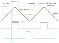
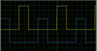
Requesting you just to clarify the ISR logic a little more. Expected signal for bridge drive should look like the attached image.

pwm-for-converter(50kHz).png
 
Last edited:

fast pwm is not work properly for this, and one output must be set on compare match -
TCCR1A=(1<<COM1A1)|(1<<COM1B1)|(1<<COM1B0)|(1<<WGM11);


or possible to switch outputs in each interruption

Code:
/*****************************************************
CVAVR V2.05
Chip type               : ATmega8
AVR Core Clock frequency: 8 MHz
*****************************************************/
#include <mega8.h>


void t1_cfg()
{
 TCCR1A=1<<COM1A1|1<<COM1A0|1<<WGM11; //out A set on comp, out B off
 TCCR1B=1<<WGM13|1<<WGM12|1<<CS10;   //fast pwm top ICR  
 ICR1=320/2;   //for 8MHz  
 OCR1A=OCR1B=0;
 TIMSK|=1<<TOIE1;  
}
void gpio_cfg()
{
 PORTB=0; DDRB =0b00000110;
}

interrupt [TIM1_OVF] void t1_ovf_isr()
{
 #define dtv 40 //dead time val  
 #define pdr 100 // dtv < must be < top pwm
 TCCR1A ^= 1<<COM1A1|1<<COM1A0|1<<COM1B1|1<<COM1B0; //switching outputs
 OCR1A=OCR1B=pdr;
 
}

void main(void)
{
gpio_cfg();
t1_cfg();

#asm("sei")
while (1)
      {}
}

- - - Updated - - -

and, in last case, dtv must be sufficient for switching, i think >25
 
Last edited:

You told that Fast PWM will not work properly. Later you gave code with Fast PWM.

I'm trying to make the signal using Phase Correct PWM by following your illustration (attached image). As I'm working with Arduino uno (ATMega328), I'm trying to write program using ATMega328 mcu. Here is my revised code -

Code:
#define TOP 160;
#define dt 16;

int duty=0; //a varibale by which time period can be varied 
void setup()
{
  DDRB=(1<<PINB1)|(1<<PINB2); //OC1A and OC1B as output  
  
  TCCR1A=(1<<COM1A1)|(1<<COM1A0); //set OC1A at match on up counting, clear on down counting ; Phase correct
  OCR1A=0;
  OCR1B=0;
  ICR1=TOP; 
  TIMSK1=(1<<TOIE1);

  TCCR1B=(1<<WGM13)|(1<<CS10);  //phase correct and no prescaling
  
 sei();
}

void loop()
{

}

ISR(TIMER1_OVF_vect)
{ 
  TCCR1A^=(1<<COM1B1); //clear OC1B on compare match up counting, set on down counting
  OCR1A=80+dt+duty;  //TOP/2=80
  OCR1B=80-dt-duty;  //TOP/2=80
  	
}

Seeing your illustration it seemed that I had understood the basics of generating the required signal using phase correct mode. But my code is not giving the expected output :sad:
arduinoPWM.png
 
Last edited:

You told that Fast PWM will not work properly. Later you gave code with Fast PWM.
sure, for {OCR1A=some value; OCR1B=pwm top - OCR1A;} fast pwm is not work properly.

code for ATMega328 & phase correct pwm -

Code:
/*****************************************************
CVAVR V2.05.0 Professional
Chip type               : ATmega328P
AVR Core Clock frequency: 8,000000 MHz
*****************************************************/
#include <mega328p.h>

flash int TOP = 160; //25kHz
flash int dt = 16;
int duty; //a varibale by which time period can be varied 

void gpio_init(){DDRB=1<<1|1<<2;}
void t1_init()
{
TCCR1A = 1<<COM1A1|1<<COM1B1|1<<COM1B0|1<<1;
TCCR1B = 0x11;
OCR1AH=OCR1BH=0;
ICR1L=TOP; 
//TIMSK1=(1<<TOIE1);
}
/*
interrupt [TIM1_OVF] void t1_ovf_isr()
{
}
*/


void main(void)
{
gpio_init();
t1_init();

duty=25;

if(dt<TOP/2)
    {
     if(duty<TOP/2-dt){OCR1AL=duty;OCR1BL=TOP-duty;}
     else{OCR1AL=1;OCR1BL=TOP-1;}
    }
else{OCR1AL=1;OCR1BL=TOP-1;}

// Crystal Oscillator division factor: 1
#pragma optsize-
CLKPR=0x80;
CLKPR=0x00;
#ifdef _OPTIMIZE_SIZE_
#pragma optsize+
#endif
  
#asm("sei")

while (1) {}
}

- - - Updated - - -

code for ATMega328 & fast pwm -
Code:
/*****************************************************
CVAVR V2.05.0 Professional
Chip type               : ATmega328P
AVR Core Clock frequency: 8,000000 MHz
*****************************************************/
#include <mega328p.h>

flash int TOP   = 160; //25kHz
flash int dt    = 16;
      int duty  = 150; //a varibale by which time period can be varied 

void gpio_init(){DDRB=1<<1|1<<2;}
void t1_init()
{
TCCR1A=0b11000010;
TCCR1B=0x19;
OCR1AH=OCR1BH=ICR1H=0;
ICR1L=TOP; 
TIMSK1=(1<<TOIE1);  
}

interrupt [TIM1_OVF] void t1_ovf_isr()
{
 TCCR1A ^= 0b11110000;
 OCR1AL=OCR1BL=duty;  
}


void main(void)
{
gpio_init();
t1_init();

 
 if((duty<TOP)&&(duty>dt)) {} 
 else duty=TOP-1;

// Crystal Oscillator division factor: 1
#pragma optsize-
CLKPR=0x80;
CLKPR=0x00;
#ifdef _OPTIMIZE_SIZE_
#pragma optsize+
#endif
  
#asm("sei")

while (1) {}
}
 
Last edited:

Thanks a lot for your continuous support.

I'm trying to understand the algorithm for both the case (Fast and Phase correct). I'll understand and write my won code and show to you. The problem is I'm using Arduino now. Your code cannot be used directly. As there is no debugger or simulator to test my code. I've to upload the program in arduino chip to test.

Previously I used to do some basic program for PIC using MPLAB which was a great tool. It has a logic analyzer to observe the waveforms. In ATMEL Studio I did not find such. :sad: Could you please suggest any good simulator/debugger for AVR?
 

Thanks a lot for your continuous support.
this because i think in same direction )

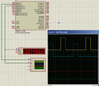
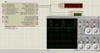
I use Code Vision AVR & Proteus 7.7 for AVR simulation, it is also great tool. In simple event no needs real hardware with it.
 
Last edited:

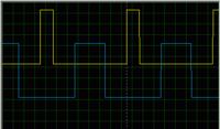
I've understood the algorithm used in your code. I've made my own code for Arduino. It is giving the correct waveform

Code:
#define TOP 160;
#define dt 16;

int duty=40; //a variable by which on time (duty cycle) can be varied 
void setup()
{
  DDRB=(1<<PINB1)|(1<<PINB2); //OC1A and OC1B as output  
  
  TCCR1A=(1<<COM1B1)|(1<<COM1B0); //set OC1A at match on up counting, clear on down counting ; Phase correct
  OCR1A=0;
  OCR1B=0;
  ICR1=TOP; 
  //TIMSK1=(1<<TOIE1);
  TCCR1A^=(1<<COM1A1); //clear OC1B on compare match up counting, set on down counting
  TCCR1B=(1<<WGM13)|(1<<CS10);  //phase correct and no prescaling  
 //sei();
}

void loop()
{
 OCR1A=80-duty;  //TOP/2=80
 OCR1B=80+duty;  //TOP/2=80
}

Duty cycle can be changed by changing the value of duty.

But If I use a constant dead time (dt=16) in the expression, it doesn't work. i.e, duty cycle cannot be varied by varying the duty variable -
Code:
void loop()
{
 OCR1A=80-dt-duty;  //TOP/2=80
 OCR1B=80-dt+duty;  //TOP/2=80
}

It seems to be the issue of programming. May be, a constant defined in a form of macro (#define ...) and a general variable (int ...) cannot be used at a time. I couldn't remember whether there was such thing I read in programming classes couple of years ago.
 

Code:
{
#define dt 16
 int duty=40;

 OCR1A=80-dt-duty;  //OCR1A=24,  pulse duration OCR1A*2= 48
 OCR1B=80-dt+duty;  //OCR1B=104, pulse duration (160-OCR1B)*2= 112
}

Code:
{
 if(duty<80-dt) {OCR1A=duty;}//OCR1A=40,  pulse duration OCR1A*2= 40*2
 OCR1B=160-duty; //OCR1B=120,  pulse duration (160-OCR1B)*2= 40*2
}
 

Status
Not open for further replies.

Similar threads

Part and Inventory Search

Welcome to EDABoard.com

Sponsor

Back
Top