adnan012
Advanced Member level 1
Hi,
I am working on Push-Pull DC/DC converter which is a part of modified sine wave inverter.
The following specs are desired.
Input voltage range: 10.5 -21VDC
Output 800Watts when input is 10.5-14VDC
Output 350Watts when input is 15-21VDC
I am using TL494 PWM controller configured as push pull.
Transformer is PQ32/30 core. Switching frequency is 40KHz.
There are 3 + 3 Primary turns of 0.25mm thick copper strip and 33 (Litz wire) turns on secondary side.
This transformer is only for testing purpose.
Open Loop Testing:
For testing the input source is high power linear power supply.
Digital load is used for loading the DC/DC converter.
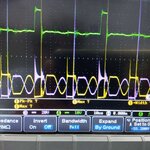
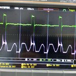
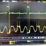
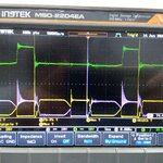
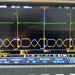
In open loop test the duty cycle is fixed and is set to 43%. The input voltage are varied from 10.5 -18VDC. I get 120VDC when the input voltage is 16VDC and load is around 700 to 800Watts and the efficiency is 85%.
There is no issue with the DC/C section. The input current varies when the load is changed or when the input voltage are changed.
Closed Loop Testing:
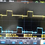
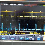
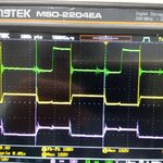
I am facing issue in closed loop test. When feedback is present (both primary and secondary grounds are common in this case) I have the following scenario
Digital load is set to 1 amp.
Output voltage is set to 90VDC .
The output voltage are stable when the input is changed from 11VDC to 18DVC (or more) and Duty cycle also become very narrow in case of high input voltage. But the input current always remain same and at high input voltage the efficiency goes to 60%.
I need help to resolve this issue.
I am working on Push-Pull DC/DC converter which is a part of modified sine wave inverter.
The following specs are desired.
Input voltage range: 10.5 -21VDC
Output 800Watts when input is 10.5-14VDC
Output 350Watts when input is 15-21VDC
I am using TL494 PWM controller configured as push pull.
Transformer is PQ32/30 core. Switching frequency is 40KHz.
There are 3 + 3 Primary turns of 0.25mm thick copper strip and 33 (Litz wire) turns on secondary side.
This transformer is only for testing purpose.
Open Loop Testing:
For testing the input source is high power linear power supply.
Digital load is used for loading the DC/DC converter.
In open loop test the duty cycle is fixed and is set to 43%. The input voltage are varied from 10.5 -18VDC. I get 120VDC when the input voltage is 16VDC and load is around 700 to 800Watts and the efficiency is 85%.
There is no issue with the DC/C section. The input current varies when the load is changed or when the input voltage are changed.
Closed Loop Testing:
I am facing issue in closed loop test. When feedback is present (both primary and secondary grounds are common in this case) I have the following scenario
Digital load is set to 1 amp.
Output voltage is set to 90VDC .
The output voltage are stable when the input is changed from 11VDC to 18DVC (or more) and Duty cycle also become very narrow in case of high input voltage. But the input current always remain same and at high input voltage the efficiency goes to 60%.
I need help to resolve this issue.