Continue to Site

Welcome to EDAboard.com

Welcome to our site! EDAboard.com is an international Electronics Discussion Forum focused on EDA software, circuits, schematics, books, theory, papers, asic, pld, 8051, DSP, Network, RF, Analog Design, PCB, Service Manuals... and a whole lot more! To participate you need to register. Registration is free. Click here to register now.

Push-Pull center tap converter transformer design

Status
Not open for further replies.

emreozer

Member level 2
Joined
Nov 13, 2006
Messages
45
Helped
1
Reputation
2
Reaction score
0
Trophy points
1,286
Location
Istanbul - Turkey
Activity points
1,572
I need your opinions!!.

The input voltage is 9 to 15 VDC.
Output voltage is 250 VDC.
Output current is about 2-3 A.
Operating frequency 55 KHz.
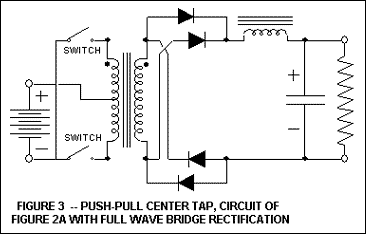
The push-pull is a center tapped version.

Anybody help me about core selection and transformer turn calculation?

thanks
 

Hi Emreozer
I've a good suggestion for you !
take a look here , please ! from page one up to the latest page ! i'll bet that you'll find all you need , there !
https://www.edaboard.com/threads/229615/
Best Wishes
Goldsmith
 
Thank you very much. But I'm looking for a design consideration and procedure like attached file.
 

Attachments

  • an109.pdf
    58.1 KB · Views: 294

Thank you very much. But I'm looking for a design consideration and procedure like attached file.
What do you mean by like the attached file ?
Is your mean , this method ? can you clarify your meaning ?
 
Ok so I calculated my transformer, need your opinion !
My need is a 12 VDC -> 250VDC, 500 W push-pull converter, oprating frequency 55 KHz. But I want to use multiple transformers, primary in parallel and secondary in serie. I will try to obtain 600W with 2 ETD49 transformer, N87 material, and full bridge topology.

I want to learn design consideration.

Regards,
Emre
Emre , i thought you've read that thread exactly ! because you can design magnetic elements with that thread for pretty large powers as well ( from some watts up to some hundred kilo watts )
Design considerations ! this is what i've explained there and all i can say !
Anywhere ,
But I want to use multiple transformers, primary in parallel and secondary in serie. I will try to
may you tell me , what do you mean by primary in parallel ? is your mean , to yield 500 watts you want use wires in parallel together ? if yes of course you've to do it to prevent skin effect . is your mean how to calculated what number of wire should be twisted in parallel and how ?
 
Primary in parallel doesnt matter. Actually I'm interested in transformer calculation and core selection.

4022470500_1352976075.gif
 

Let's take your requirements as an example. You're using 2 transformers for 600W. So, each transformer should handle 300W.

So, your voltage conversion requirement is 12VDC to 250VDC.

You stated the minimum voltage as 9V. So, you'd still need 250VDC at that input voltage. Let's take maximum duty cycle as 95%. So, at 9VDC input, duty cycle will be maximum. Average voltage to transformer will be 9V * 0.95 = 8.55V. Thus voltage ratio is (250V/8.55V) = 29.24. Let's leave some headroom to allow for losses and voltage drops and some headroom for feedback. So, let's take a voltage ratio of (270V/8.55V) = 31.6.

Formula for calculating primary turns is:

Npri = (Vinnom * 10^8) / (4 * f * Bmax * Ac)

Ac (or sometimes called Ae) is in cm^2, Bmax is in Gauss, f is in Hertz, Vinnom is in Volts.

Get Ac and Bmax from transformer datasheet.

For ETD49, from the datasheet I have, I get Ac = 2.36
I'll take Bmax to be 1800. Most cores should be okay with that. Make sure though.
Vinnom = 12V
f = 55000

So, I get Npri = 1 turn (rounded off)
Check Bmax.
Bmax (with Npri = 1) comes out to 2311. If that's too high, increase Npri to 2. So, Bmax comes out to 1156. That should be okay.

Nsec = (Turns Ratio) * Npri
Turns Ratio = Voltage Ratio = 31.6
With Npri = 1, Nsec = 32 (rounded off).
With Npri = 2, Nsec = 63 (rounded off).

Now, wind with a sufficient number of thin wires in parallel to minimize wire resistance and skin effect. Or use Litz wire.

There you have it.

Hope this helps.
Tahmid.
 
Last edited:
Thank you very much for your help.

I have a few more questions.
Which datasheet did you get some values about core?
I found one, but there is no information about Bmax.

Other subject; which wire size should I use to wind transformer?
maybe firtsly I have to calculate current capacity or skin depth?
 

Attachments

  • etd_49_25_16.pdf
    73.9 KB · Views: 222

There are EPCOS material data sheets that contain all information you possibly want to read. Bmax isn't a relevant parameter for 100 kHz operation frequency, however. If you read the linked datasheet thoroughly. you'll notice that B = 200 mT (about half Bmax) is assumed for Pv calculation, which sounds more reasonable.

Winding Rac considering skin and proximity effect can be calculated along with many other interesting parameters by the Ferrite tool downloadable from EPCOS.
 
As stated by FvM, the datsheet you attached shows Pv calculation witth B = 200mT at 100kHz.

200mT = 2000G [1T = 10000G]

EPCOS Ferrite Magnetic Design Tool:

Hope this helps.
Tahmid.
 
Status
Not open for further replies.

Similar threads

Part and Inventory Search

Welcome to EDABoard.com

Sponsor

Back
Top