Continue to Site

Welcome to EDAboard.com

Welcome to our site! EDAboard.com is an international Electronics Discussion Forum focused on EDA software, circuits, schematics, books, theory, papers, asic, pld, 8051, DSP, Network, RF, Analog Design, PCB, Service Manuals... and a whole lot more! To participate you need to register. Registration is free. Click here to register now.

purchase of tunable lowpass filter

Status
Not open for further replies.

s55

Junior Member level 2
Joined
Mar 21, 2013
Messages
21
Helped
0
Reputation
0
Reaction score
1
Trophy points
1,283
Activity points
1,537
I'm looking for a tunable lowpass filter to be used between a signal generator's output and an input of an ADC. Basically, it works as an antialiasing filter.

The desired frequency specifications of this tunable filter are as follws:
start frequency - dc,
stop frequency - 20~50MHz which can be selectively set.

I searched several vendors, but most tunable filters' stop frequencies are few tens kHz. Is there anybody who knows vendors to provide such tunable lowpass filter with the spec as above?
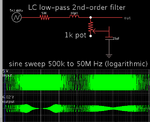
 

It may not be possible to dial your entire frequency range with one potentiometer and a fixed RC (or RCRC) network. You can expect to need several ranges, selectable one at a time. Each range switches in a different RC combination, having a different time constant.

There are op amp (active) filter schematics although you'd need a speedy op amp, since your cutoff frequency is in the rf spectrum.

You may decide that inductors are more useful than capacitors for certain ranges.
 

There are filters known as rf traps or wavetraps, which can be purchased in different types of filters and for different bands of frequencies.
 

Here is an example of a simple low-pass filter which can be made tunable. LC second-order filter. A potentiometer varies resistance through the capacitor. This changes the sharpnesss of the rolloff curve.

low-pass LC 2nd order filter cap has var resis sweep 500k-50M.png

Halfway through the run, the potentiometer was moved from top to bottom. The effect is visible near the 50MHz point, comparing one half of the sweep with the other half.

- - - Updated - - -

An inductor value of 10 uH is easy and quick to wind. Your equipment may have a different resistance than my simulation shows at the source (500 ohms). So you'll need to experiment with values, to obtain the performance you want.
 
  • Like
Reactions: s55

    s55

    Points: 2
    Helpful Answer Positive Rating
Status
Not open for further replies.

Similar threads

Part and Inventory Search

Welcome to EDABoard.com

Sponsor

Back
Top