symba05
Newbie level 2
Hello good people of this forum!
I don't have a lot of experience with VHDL and I need some help to create a VHDL code for this situation:
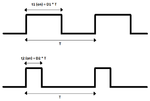
Draw a control circuit that generates a pulse signal with:
fixed working frequency (100 KHz)
variable working cycle
The phase difference should be increased or decreased by the direction of the spin of a rotary control of 8 bits.
Additional info: D = t (on) / T
D = working cycle
t (on) = Time the activated signal lasts
T = signal period (constant)
(see the signal in the image attached)
