Continue to Site

Welcome to EDAboard.com

Welcome to our site! EDAboard.com is an international Electronics Discussion Forum focused on EDA software, circuits, schematics, books, theory, papers, asic, pld, 8051, DSP, Network, RF, Analog Design, PCB, Service Manuals... and a whole lot more! To participate you need to register. Registration is free. Click here to register now.

Pulse Generator Without Using NE555

ahmetkara4635

Newbie
Joined
May 1, 2024
Messages
5
Helped
0
Reputation
0
Reaction score
0
Trophy points
1
Activity points
46
As a project assignment, we were asked to design a signal generator. A variable amplitude between 80 mV and 2V. A variable frequency between 355 Hz and 3 KHz and duty between 10% and 90%.
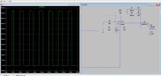
As a result of my research, I found the Pulse section as follows. I have two problems. First, as the duty changes, the frequency also changes. I control the second output voltage with a voltage divider and I get the correct result only when the value of the pot is maximum and minimum.
 

Attachments

  • 2.jpg
    2.jpg
    171.7 KB · Views: 52
  • 2.jpg
    2.jpg
    171.7 KB · Views: 45
Hint, you have 3 basic R's that control....

The variable R U7 controls hysteresis of the LM308 being used as a comparator. So yes
it changes trip level AND the freq....So what R would only change the freq, and what R
would control duty cycle ?

Regards, Dana.
 
I am controlling duty cycyle R17 and R8. When I want to control frequency I am using pot U7. But when I change the duty my also my frequency changing and my circuit is not working stable. The circuit is have a voltage divider at the end. But this is not linear.

Regards, Ahmet.
 
I know what you are doing and what result you are getting. I am suggesting
changing what R you use to control freq........
 
If you want separate and completely decoupled frequency and duty cycle control, use two stages, a variable frequeny triangle generator and a comparator converting the triangle to variable duty cycle square wave.
 
Hi,

Almost perfect frequency control and duty cycle control can be done using a microcontroller.
You can be sure then that adjusting one value does not influence the other value.

A cheap microcontroller and a view lines of code will do.
Using Arduino boards and Arduino IDE ... also enables you to use code freely available on the internet. This minimizes coding effort.
The only thing you need to do "externally" is the voltage control ... in simplest case just by using a potentiometer.

***
I personally prefer the digital solution., mainly because
* no need to build your hardware
* almost perfect timing control (using PWM module)
* stable timing (no aging drift, no thermal drift, no power supply related drift)
* adjustable (which you don´t describe "how) can be in various ways: via pot and ADC, UART, USB, IR remote control.... automaticall following any algorithm...

****
Even the "amplitude control" could be easily done "digitally controlled": Just use a second PWM to adjust amplitude using external RC low pass filter. Then a simple external analog switch (controlled by the first PWM) ....

****
You should also tell us whether this is a school project .. or a real application.

Klaus
Thanks for your recommends.This is my assignment. And the IC's are banned. Like microchips,NE555. Only opamps and logic gates are available.
Ahmet
 
If you want separate and completely decoupled frequency and duty cycle control, use two stages, a variable frequeny triangle generator and a comparator converting the triangle to variable duty cycle square wave.
I thought this and I did it today. But I have some problems. Firstly. I made a Schmitt-Trigger,and I integrated the output signals. So I have a triangular wave. And then I try to rectify the Triangular Wave. And finally I used a comparator. But my rectify circuit is include Op-Amps because when I try the rectify it with Bridge Rectifier it doesn't work I don't know why. In LTspice my circuit is working not bad. The problem is in Simulation rings in pulse. On the other hand problem is in the real life the rectifier not working good. I receive very bad rectified wave. But my integrator is working very good.
 

Attachments

  • pulse.PNG
    pulse.PNG
    34.9 KB · Views: 24
  • pulse1.PNG
    pulse1.PNG
    72.2 KB · Views: 25
  • pulse oscillator.jpg
    pulse oscillator.jpg
    126.2 KB · Views: 25
Why rectify it?
Once you have a triangle wave you can feed it straight to a comparator circuit and compare it to a voltage adjustable above and below zero. The comparator output may go from +v to -v but you can use a diode to clip or clamp the negative side at the output if necessary.

Brian.
 
These can be independently controlled if done in this order.

1. Frequency between 355 Hz and 3 kHz
2. Duty cycle between 10% and 90%.
3. Amplitude between 80 mV and 2V

Not stated is the DC output or if the units are +/- Vpk, Vp-p or 0~Vpk
 
If you look at the basic circuit your opamp serves as a window comparator, but also affects
freq because as the window changes the time the RC needs to charge / discharge changes. But
affecting the window trip points changing the amplitude achieved at the inverting input
to opamp to hit the trip points, negative and positive.

The charge and discharge RC time constant is affected by your diode / R fdbk values, so those
Rs affect duty cycle, but also affect frequency as they alter how fast / slow the charge and discharge
paths work. Note also the output swing of the OpAmp used as comparator is inherently not symmetrical,
causing offset error in the duty cycle. And the diodes, being ~.7V in Vforward also affect minimum duty
cycle achievable. And of course saturated comparator outputs and/or diodes exhibit a lot of T affect
drift in V, aggravating performance even more. And comparators with saturated outputs have no PSRR
of output values, so changes on supply rails affect output levels.


So in short the architecture needs help if you want independent controls over freq, duty cycle, amplitude.


Regards, Dana.
 
Last edited:

LaTeX Commands Quick-Menu:

Similar threads

Part and Inventory Search

Welcome to EDABoard.com

Sponsor

Back
Top