biswajitdas49
Member level 3

- Joined
- May 17, 2012
- Messages
- 55
- Helped
- 0
- Reputation
- 0
- Reaction score
- 0
- Trophy points
- 1,286
- Location
- WEST BENGAL,INDIA
- Activity points
- 1,726
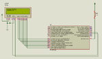
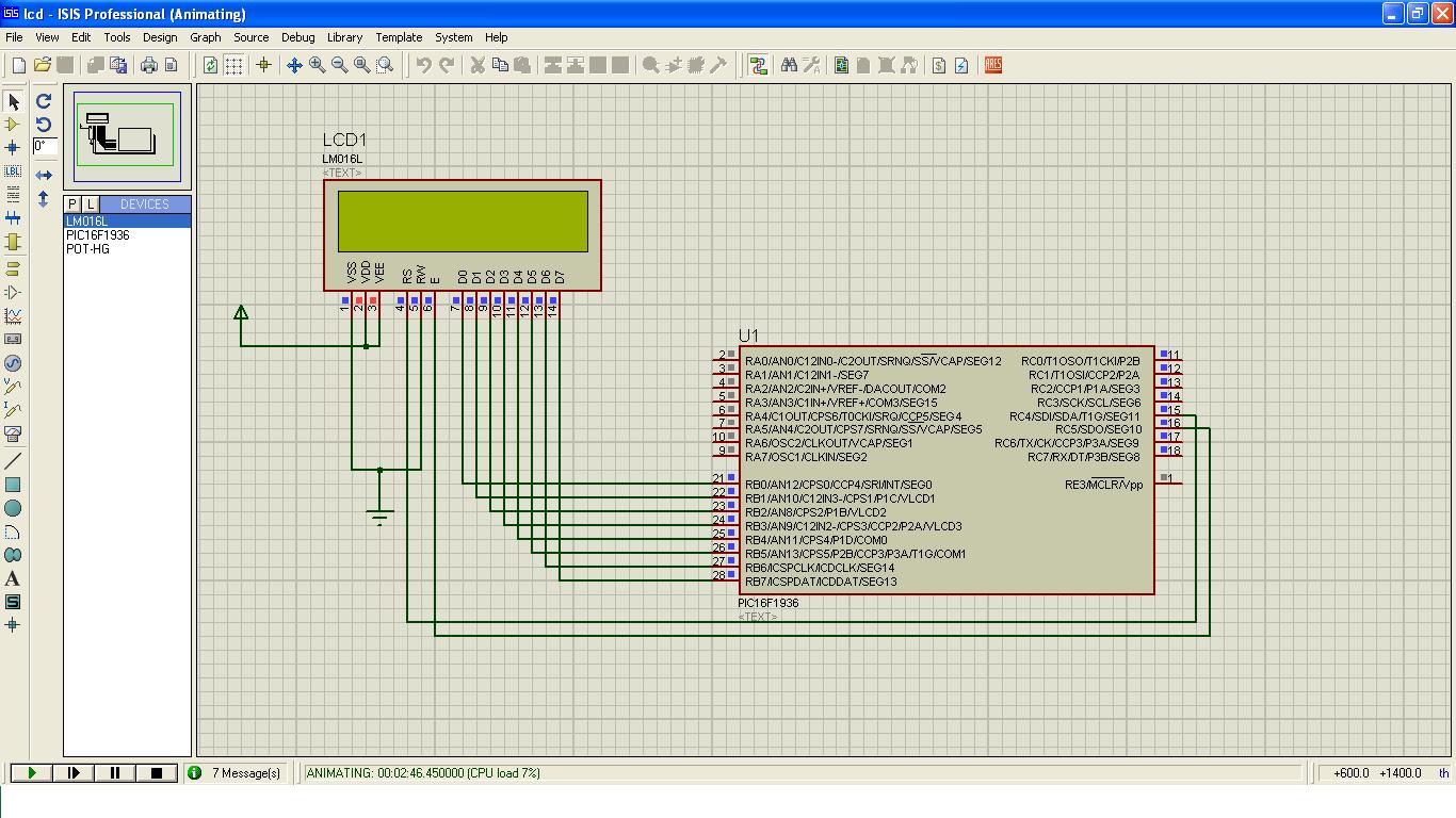
I write a code in assembly for 16x2 lcd display,but it does not display the ASCII code which given in the code.I use pic16f1936 uC at 4 MHz internal osc. My display interface is 8 bit mode with my controller.
Now my problem is when I start the animation play button, all the connected pin work as well,but it display nothing.I don't understand what's wrong with my code or the pin connection,or anything else may be connected with this pin.
please some body help me!!!!!!!!!!!!!
my proteus lcd interface image is here-

here is my code:-
Now my problem is when I start the animation play button, all the connected pin work as well,but it display nothing.I don't understand what's wrong with my code or the pin connection,or anything else may be connected with this pin.
please some body help me!!!!!!!!!!!!!
my proteus lcd interface image is here-
here is my code:-
Code:
;******************************************************************************
;   This file is a basic code template for code generation on the             *
;   PIC16F1936. This file contains the basic code building blocks to build    *
;   upon.                                                                     *
;                                                                             *
;   Refer to the MPASM User's Guide for additional information on             *
;   features of the assembler.                                                *
;                                                                             *
;   Refer to the respective data sheet for additional                         *
;   information on the instruction set.                                       *
;                                                                             *
;******************************************************************************
;                                                                             *
;    Filename:        xxx.asm                                                 *
;    Date:                                                                    *
;    File Version:                                                            *
;                                                                             *
;    Author:                                                                  *
;    Company:                                                                 *
;                                                                             *
;                                                                             *
;******************************************************************************
;                                                                             *
;    Files Required: P16F1936.INC                                             *
;                                                                             *
;******************************************************************************
;                                                                             *
;    Notes:                                                                   *
;                                                                             *
;******************************************************************************
;                                                                             *
;    Revision History:                                                        *
;                                                                             *
;******************************************************************************


	list		p=16f1936      ; list directive to define processor
	#include	<p16f1936.inc> ; processor specific variable definitions

;------------------------------------------------------------------------------
;
; CONFIGURATION WORD SETUP
;
; The 'CONFIG' directive is used to embed the configuration word within the
; .asm file. The lables following the directive are located in the respective
; .inc file.  See the data sheet for additional information on configuration
; word settings.
;
;------------------------------------------------------------------------------

    __CONFIG _CONFIG1, _FOSC_INTOSC & _WDTE_OFF & _PWRTE_OFF & _MCLRE_ON & _CP_OFF & _CPD_OFF & _BOREN_OFF & _CLKOUTEN_ON & _IESO_OFF & _FCMEN_OFF
    __CONFIG _CONFIG2, _WRT_OFF & _VCAPEN_OFF & _PLLEN_OFF & _STVREN_OFF & _BORV_19 & _LVP_OFF

;------------------------------------------------------------------------------
; VARIABLE DEFINITIONS
;
; Available Data Memory divided into Bank 0-15.  Each Bank may contain
; Special Function Registers, General Purpose Registers, and Access RAM
;
;------------------------------------------------------------------------------
	#DEFINE RS PORTC,4				;pin no.15
	#DEFINE EN PORTC,5				;pin no.16
;	#DEFINE DB7 PORTD,3
;	#DEFINE DB6 PORTD,2
;	#DEFINE DB5 PORTD,1
;	#DEFINE DB4 PORTD,0
	#DEFINE   LINE1    0x80


    CBLOCK 0x20 ; Define GPR variable register locations
		LCD_CMD
		LCD_DATA
		PORTD_TEMP
		VALUE_REG
		VALUE_REG1
		CounterA
		CounterB
		CounterC
		CounterD
    ENDC

SAMPLE1        EQU    0x7D        ; Sample user registers
SAMPLE2        EQU    0x7E        ;
SAMPLE3        EQU    0x7F        ;

;------------------------------------------------------------------------------
; EEPROM INITIALIZATION
;
; The 16F1936 has 256 bytes of non-volatile EEPROM, starting at address 0xF000
;
;------------------------------------------------------------------------------


DATAEE    ORG  0xF000
    DE    "MCHP"  ; Place 'M' 'C' 'H' 'P' at address 0,1,2,3

;------------------------------------------------------------------------------
; RESET VECTOR
;------------------------------------------------------------------------------

    ORG     0x0000            ; processor reset vector
    PAGESEL START
    GOTO    START             ; When using debug header, first inst.
                              ; may be passed over by ICD2.

;------------------------------------------------------------------------------
; INTERRUPT SERVICE ROUTINE
;------------------------------------------------------------------------------

    ORG      0x0004

;------------------------------------------------------------------------------
; USER INTERRUPT SERVICE ROUTINE GOES HERE
;------------------------------------------------------------------------------

; Note the 16F1936 family automatically handles context restoration for
; W, STATUS, BSR, FSR, and PCLATH where previous templates for 16F families
; required manual restoration

    RETFIE                    ; return from interrupt

;------------------------------------------------------------------------------
; MAIN PROGRAM
;------------------------------------------------------------------------------

START

;------------------------------------------------------------------------------
; PLACE USER PROGRAM HERE
;------------------------------------------------------------------------------
CALL INITIALIZATION
CALL LCD_INIT
CALL SEND_DATA

GOTO $

INITIALIZATION
	BANKSEL OSCCON
	MOVLW B'01101010'		;Fosc 4MHZ
	MOVWF OSCCON

	BANKSEL PORTC
	CLRF PORTC
	BANKSEL LATC
	CLRF LATC
	BANKSEL TRISC
	CLRF TRISC

	banksel PORTB
	clrf PORTB
	banksel ANSELB
	clrf ANSELB

	banksel TRISB
	CLRF TRISB
RETURN

LCD_INIT
	CALL LONG_DELAY
	MOVLW B'00110000' 			;Function set
	CALL WRITE_CMD
	MOVLW B'00110000'			;Function set
	CALL WRITE_CMD
	MOVLW B'00110000'			;Function set
	CALL WRITE_CMD
	MOVLW B'00111000'			;Sets to 8-bit operation and selects 2-line display and 5*8 dot character font
	CALL WRITE_CMD
	MOVLW B'00001000'			;Turns on display and cursor,All display is in space mode because of initialization.
	CALL WRITE_CMD
	MOVLW B'00000001'
	CALL WRITE_CMD
	MOVLW B'00000110'
	CALL WRITE_CMD
	MOVLW B'00001100'
	CALL WRITE_CMD
	MOVLW B'10000000'
	CALL WRITE_CMD
	CALL LONG_DELAY
RETURN

SEND_DATA

		MOVLW A'S'
	CALL WRITE_DATA
		MOVLW A'W'
	CALL WRITE_DATA
		MOVLW A'A'
	CALL WRITE_DATA
		MOVLW A'J'
	CALL WRITE_DATA
		MOVLW A'I'
	CALL WRITE_DATA
		MOVLW A'T'
	CALL WRITE_DATA
		MOVLW A'T'
	CALL WRITE_DATA
RETURN


WRITE_CMD

	BANKSEL PORTB
	MOVWF PORTB
	BANKSEL PORTC
	BCF PORTC,4		;RS pin
;	CALL DELAY_5mS
	BSF PORTC,5		;enable pin
	CALL DELAY_200uS
	BCF PORTC,5
;	CALL DELAY_40mS
RETURN

WRITE_DATA

	BANKSEL PORTB
	MOVWF PORTB
	BANKSEL PORTC
	BSF RS
;	CALL DELAY_5mS
	BSF PORTC,5
	CALL DELAY_200uS
	BCF PORTC,5
;	CALL DELAY_40mS
BSF PORTB,0

RETURN

LONG_DELAY
		movlw	D'16'
		movwf	CounterC
		movlw	D'57'
		movwf	CounterB
		movlw	D'205'
		movwf	CounterA
loop0
		decfsz	CounterA,1
		goto	loop0
		decfsz	CounterB,1
		goto	loop0
		decfsz	CounterC,1
		goto	loop0
		retlw	.0

DELAY_40mS
		movwf	CounterB
		movlw	D'241'
		movwf	CounterA
loop1
		decfsz	CounterA,1
		goto	loop1
		decfsz	CounterB,1
		goto	loop1
		retlw	.0


DELAY_5mS
		movlw	D'7'
		movwf	CounterB
		movlw	D'231'
		movwf	CounterA
loop2
		decfsz	CounterA,1
		goto	loop2
		decfsz	CounterB,1
		goto	loop2
		retlw	.0


DELAY_200uS
		movlw	D'26'
		movwf	CounterB
		movlw	D'247'
		movwf	CounterA
loop3
		decfsz	CounterA,1
		goto	loop3
		decfsz	CounterB,1
		goto	loop3
		retlw	.0


DELAY_53uS
		movlw	D'7'
		movwf	CounterB
		movlw	D'224'
		movwf	CounterA
loop4
		decfsz	CounterA,1
		goto	loop4
		decfsz	CounterB,1
		goto	loop4
		retlw	.0


    END
Last edited by a moderator: