Continue to Site

Welcome to EDAboard.com

Welcome to our site! EDAboard.com is an international Electronics Discussion Forum focused on EDA software, circuits, schematics, books, theory, papers, asic, pld, 8051, DSP, Network, RF, Analog Design, PCB, Service Manuals... and a whole lot more! To participate you need to register. Registration is free. Click here to register now.

Proteus simulation of MOSFET Voltage inverter gives DC output, How to correct this?

Status
Not open for further replies.

umat

Newbie level 3
Joined
Mar 12, 2017
Messages
3
Helped
0
Reputation
0
Reaction score
0
Trophy points
1
Activity points
24
Hello,

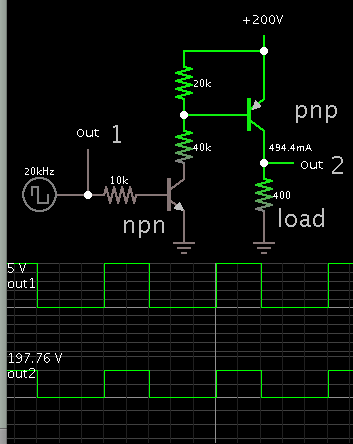
My DC to AC converter circuit (attached) does not produce AC output. I have connected a pulse generator to one pair of the bridge switches. The other pair is connected from the same pulse source except that the inputs are inverted through a not gate.

PowerInverter.jpg

I intend to replace the pulse generators with microcontroller PWMs after I get the circuit working.

Kind regards.
 

Your mosfets are P-type. The bias is referenced to the more positive terminal. To turn off a P-device, requires the bias voltage be same level (pretty much) as the positive supply voltage. Since your supply is 200V, then it looks as though your mosfets are never shutting off.

To get the mosfets to switch on and off, try reducing Bat3 to a lower voltage, namely the same voltage produced by U2 (invert gate).
 
  • Like
Reactions: umat

    umat

    Points: 2
    Helpful Answer Positive Rating
I have changed my transistors to N-Channel type MOSFETs, (does this seem better?) and have also changed the connections as shown below. My task is to convert a 200V DC to an AC value, hence Vbat is 200V.

powerConverter3.png

Is there any way I can switch on and off the MOSFETs with my without changing my Vbat?
 

Flipping supply voltage and transistor polarity doesn't turn it into a working circuit. Looks like you have seen a principle schematic of a full bridge and thought it a real circuit.

You need isolated or level shifting gate drivers for the high side. Also dead time generation to avoid bridge shoot-through.
 
  • Like
Reactions: umat

    umat

    Points: 2
    Helpful Answer Positive Rating
Is there any way I can switch on and off the MOSFETs with my without changing my Vbat?

Typical method, low voltage signal controls high voltage to load.

4118106800_1489469561.png


- - - Updated - - -

The 40k resistor needs to be adjusted so it provides desired performance. It dissipates 1W of heat with my simulation parameters. It will be a different amount in your circuit.
 
  • Like
Reactions: umat

    umat

    Points: 2
    Helpful Answer Positive Rating
Flipping supply voltage and transistor polarity doesn't turn it into a working circuit. Looks like you have seen a principle schematic of a full bridge and thought it a real circuit.

You need isolated or level shifting gate drivers for the high side. Also dead time generation to avoid bridge shoot-through.

I'll incorporate gate drive circuit for my MOSFETs or opt for BJT transistors as used Brad's circuit
 

Status
Not open for further replies.

Part and Inventory Search

Welcome to EDABoard.com

Sponsor

Back
Top