Continue to Site

Welcome to EDAboard.com

Welcome to our site! EDAboard.com is an international Electronics Discussion Forum focused on EDA software, circuits, schematics, books, theory, papers, asic, pld, 8051, DSP, Network, RF, Analog Design, PCB, Service Manuals... and a whole lot more! To participate you need to register. Registration is free. Click here to register now.

Protected Registered PAL REV ENG

Status
Not open for further replies.

apprenticemart2

Member level 1
Joined
Jun 16, 2013
Messages
35
Helped
1
Reputation
2
Reaction score
1
Trophy points
8
Activity points
312
Hi all,

I'm trying to reverse engineer a protected PAL16R8 and am getting a little stuck and am hoping to narrow down where to focus my efforts with some help from you guys because I'm a total noob.

I'm hoping someone could peruse the text file attached and spot some patterns that I can't. The decimal 128 as an input gives an interesting output for instance.

I can fire some numbers into it and read the output. As yet I don't know exactly how this device is configured. I input a number and then maintain that on the inputs and give the device 32 clocks and read the output each time. It seems to loop around after more than 32. Some numbers loop around with less than 32 clocks.

The first bit on an input is to pin 2..9

The output is read first from pin 19..12

If the text file would be better in hex I can modify it.

In circuit the device receives a sequence of numbers and every now and then it gets an output enable signal and a value appears on the outputs which is obviously being compared to something. At the moment I am testing the device out of circuit and trying to duplicate what I see with my logic analyser. I will need to put this in a text file and am working on this now.

Any suggestions will be appreciated
Thanks
 

Attachments

  • DONGMSBtest1.TXT
    44 KB · Views: 82

I have abandoned this PAL ^ for now. It's a bit too complex for me at this early stage so I'm going to try an easier one first.
Anyone care to chime in on this one? Any help will be very much appreciated and what I learn on this one should help me with any others.

With this pal there are 3 inputs and 6 outputs. Looking with my logic analyser I can see that this device counts up to 79, but it's not a straight forward count so I presume I'm going to have to use state equations or If_Then _Else?. At the moment I'm RTFM.

I'm learning Palasm 4 v1.4 just because of how long it took me to get it working in Dosbox on it's own and with the Schematic editor, although I couldn't get the extra Palasm updates to work in Dosbox, some EMM error I think.

For this device we'll call the 3 inputs Output Enable(Grounded), CLOCK and START.

On power-up all registers are set to 0 so that is what we get out.

When START goes high we start counting from 1-12 over 12 clocks, then START goes low for one clock and we get 13 output, then START goes high for 2 clocks and we get 14 and 15, then START goes low for 64 clocks and we get 16 to 79.

Anyone got any advice?

Thanks
Martin
 

"R" PALs contain flip-flops (Registers) so it's difficult to reverse engineer their contents. You may find that repeating the same input sequence gives a different output each time.

The obvious thing to do is check the security fuse is blown first and if it isn't you can read the array contents directly. I haven't used PALASM in years but I seem to remember it had the ability to convert a fuse map back to some kind of logic description, it might be worth a try. Reading a protected device will show all fuses are blown regardless of their actual state.

May I ask why you are doing this? That PAL can't be erased so it is of little use elsewhere.

Brian.
 
Consider that number of internal states is restricted by the register bit width. In addition standard PALs have no buried register outputs, all registers are exposed to output pins. Thus decoding the internal logic is straightforward.
 
Hi Brian,
I'm not an expert Brian so I may not know exactly what's happening here.
I would like to reverse engineer the PAL in my second post because it may break eventually and I'm also curious.

The PAL is used in a device that syncs to SMPTE timecode, so what it's doing (I think) is telling a microprocessor that's attached to it when a frame of SMPTE (80 bits) has been received. If it's not valid data then it won't count properly.
I have observed this behaviour with my logic analyser and I wrote a test program on my Boardmaster 4000 and observed this out of circuit doing the same under those conditions.

The fuse is blown. I did hear about a claim that power supply glitching while applying a programming voltage might work but I think that's porkies myself. Unlike a GAL there's no dual function pins, inputs are inputs and outputs are outputs, I think so I should be confident that what I have described is what the device is doing.
Thanks
Martin
 

To decode the complete logic program, you need to apply all combinations of input and register output vectors. Using the register preload feature is the best way to achieve this.
 
I did read about that in the data sheet but I have no idea how to do that. I can find no mention of how to use this feature
I make Output Enable high and then hold the outputs in a certain state and then clock it in?
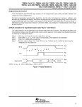
EDIT: Just found some waveform diagrams in a Ti data sheet. Looking at them now.

- - - Updated - - -

So it looks like I need to drive the Output Enable signal to +10V to make this work? Step 1, Note 3.
TI16R8_13.jpg
 

Similar to PAL programming algorithms, register preload procedures are vendor dependent, suing different pins and voltages. Need to assure that you have the correct specification for the actually used PAL type.
 

I need to duplicate a PAL16R8 that counts from 0 to 79. I will be fitting this on a PALCE16V8.

When START goes high we start counting from 1-12 over 12 clocks, then START goes low for one clock and we get 13 output, then START goes high for 2 clocks and we get 14 and 15, then START goes low for 64 clocks and we get 16 to 79.

I have had to use Wincupl for now. This is what I've managed to come up with so far but there's too many product terms for Q2.d and Q3.d.

I suppose I need to somehow make the T flip flops? Anyone have any ideas?
Thanks Martin

Code:
Name     SMPTE80 ;
PartNo   00 ;
Date     07/01/2017 ;
Revision 01 ;
Designer Engineer ;
Company  martin8or ;
Assembly None ;
Location None ;
Device   g16v8a ;


/**  Inputs  **/

Pin 1        = clk;             /* Counter clock                */
Pin 8        = start;             /* start count          */
Pin 11       = !oe;             /* Register output enable       */

/**  Outputs  **/

Pin [19..13] = [Q6..0];         /* Counter outputs              */


/** Declarations and Intermediate Variable Definitions **/

field count = [Q6..0];          /* declare counter bit field */
$define S0  'b'0000000              /* define counter states */
$define S1  'b'0000001
$define S2  'b'0000010
$define S3  'b'0000011
$define S4  'b'0000100
$define S5  'b'0000101
$define S6  'b'0000110
$define S7  'b'0000111
$define S8  'b'0001000
$define S9  'b'0001001
$define S10 'b'0001010
$define S11 'b'0001011        
$define S12 'b'0001100     
$define S13 'b'0001101
$define S14 'b'0001110
$define S15 'b'0001111
$define S16 'b'0010000
$define S17 'b'0010001
$define S18 'b'0010010
$define S19 'b'0010011
$define S20 'b'0010100
$define S21 'b'0010101          
$define S22 'b'0010110
$define S23 'b'0010111
$define S24 'b'0011000
$define S25 'b'0011001
$define S26 'b'0011010
$define S27 'b'0011011
$define S28 'b'0011100
$define S29 'b'0011101
$define S30 'b'0011110
$define S31 'b'0011111          
$define S32 'b'0100000
$define S33 'b'0100001
$define S34 'b'0100010
$define S35 'b'0100011
$define S36 'b'0100100
$define S37 'b'0100101
$define S38 'b'0100110
$define S39 'b'0100111
$define S40 'b'0101000
$define S41 'b'0101001             
$define S42 'b'0101010
$define S43 'b'0101011
$define S44 'b'0101100
$define S45 'b'0101101
$define S46 'b'0101110
$define S47 'b'0101111
$define S48 'b'0110000
$define S49 'b'0110001
$define S50 'b'0110010
$define S51 'b'0110011            
$define S52 'b'0110100
$define S53 'b'0110101
$define S54 'b'0110110
$define S55 'b'0110111
$define S56 'b'0111000
$define S57 'b'0111001
$define S58 'b'0111010
$define S59 'b'0111011
$define S60 'b'0111100
$define S61 'b'0111101        
$define S62 'b'0111110
$define S63 'b'0111111
$define S64 'b'1000000
$define S65 'b'1000001
$define S66 'b'1000010
$define S67 'b'1000011
$define S68 'b'1000100
$define S69 'b'1000101
$define S70 'b'1000110
$define S71 'b'1000111            
$define S72 'b'1001000
$define S73 'b'1001001
$define S74 'b'1001010
$define S75 'b'1001011
$define S76 'b'1001100
$define S77 'b'1001101
$define S78 'b'1001110
$define S79 'b'1001111


go1 = start ;

go2 = !start ;

/** Logic Equations **/

Sequenced count {                       /* free running counter */

present S0      if go1        next S1;
                       if go2        next S0;
                
present S1      if go1        next S2;
                if go2        next S0;
                
present S2      if go1        next S3;
                if go2        next S0;
                
present S3      if go1        next S4;
                if go2        next S0;
                
present S4      if go1        next S5;
                if go2        next S0;
                
present S5      if go1        next S6;
                if go2        next S0;
                
present S6      if go1        next S7;
                if go2        next S0;
                
present S7      if go1        next S8;
                if go2        next S0;
                
present S8      if go1        next S9;
                if go2        next S0;
                
present S9      if go1        next S10;
                if go2        next S0;

present S10	  if go1        next S11;
		  if go2        next S0;

present S11	  if go1        next S12;
		  if go2        next S0;

present S12     if go2        next S13;      /* Start input changes polarity */
                if go1        next S0;

present S13     if go1        next S14;      /* Start input changes polarity */
                if go2        next S0;

present S14     if go1        next S15;
                if go2        next S0;

present S15     if go1        next S16;      /* Start input changes polarity */
                if go2        next S0;

present S16     if go2        next S17;      /* Start input changes polarity */
                if go1        next S0;

present S17     if go2        next S18;
                if go1        next S0;

present S18     if go2        next S19;             
                if go1        next S0;

present S19     if go2        next S20; 
                if go1        next S0;

present S20     if go2        next S21;
                if go1        next S0;

present S21     if go2        next S22;
                if go1        next S0;

present S22     if go2        next S23;
                if go1        next S0;

present S23     if go2        next S24;
                if go1        next S0;

present S24     if go2        next S25;            
                if go1        next S0;

present S25     if go2        next S26;
                if go1        next S0;

present S26     if go2        next S27;
                if go1        next S0;

present S27     if go2        next S28;
                if go1        next S0;

present S28     if go2        next S29;
                if go1        next S0;

present S29     if go2        next S30;
                if go1        next S0;

present S30     if go2        next S31;           
                if go1        next S0;

present S31     if go2        next S32; 
                if go1        next S0;

present S32     if go2        next S33;
                if go1        next S0;

present S33     if go2        next S34;
                if go1        next S0;

present S34     if go2        next S35;
                if go1        next S0;

present S35     if go2        next S36;
                if go1        next S0;

present S36     if go2        next S37;           
                if go1        next S0;

present S37     if go2        next S38;
                if go1        next S0;

present S38     if go2        next S39;
                if go1        next S0;

present S39     if go2        next S40;
                if go1        next S0;

present S40     if go2        next S41;
                if go1        next S0;

present S41     if go2        next S42;
                if go1        next S0;
 
present S42     if go2        next S43;        
                if go1        next S0;

present S43     if go2        next S44;
                if go1        next S0;

present S44     if go2        next S45;
                if go1        next S0;

present S45     if go2        next S46;
                if go1        next S0;

present S46     if go2        next S47;
                if go1        next S0;

present S47     if go2        next S48;
                if go1        next S0;

present S48     if go2        next S49;          
                if go1        next S0;

present S49     if go2        next S50;
                if go1        next S0;

present S50     if go2        next S51;
                if go1        next S0;

present S51     if go2        next S52;
                if go1        next S0;

present S52     if go2        next S53;
                if go1        next S0;

present S53     if go2        next S54;
                if go1        next S0;

present S54     if go2        next S55;         
                if go1        next S0;

present S55     if go2        next S56;
                if go1        next S0;

present S56     if go2        next S57;
                if go1        next S0;
 
present S57     if go2        next S58;
                if go1        next S0;

present S58     if go2        next S59;
                if go1        next S0;

present S59     if go2        next S60;
                if go1        next S0;

present S60     if go2        next S61;          
                if go1        next S0;

present S61     if go2        next S62;
                if go1        next S0;

present S62     if go2        next S63;
                if go1        next S0;

present S63     if go2        next S64;
                if go1        next S0;

present S64     if go2        next S65;
                if go1        next S0;

present S65     if go2        next S66;
                if go1        next S0;

present S66     if go2        next S67;           
                if go1        next S0;

present S67     if go2        next S68;
                if go1        next S0;

present S68     if go2        next S69;
                if go1        next S0;

present S69     if go2        next S70;
                if go1        next S0;

present S70     if go2        next S71;
                if go1        next S0;

present S71     if go2        next S72; 
                if go1        next S0;

present S72     if go2        next S73;            
                if go1        next S0;

present S73     if go2        next S74; 
                if go1        next S0;

present S74     if go2        next S75; 
                if go1        next S0;

present S75     if go2        next S76; 
                if go1        next S0;
 
present S76     if go2        next S77; 
                if go1        next S0;

present S77     if go2        next S78; 
                if go1        next S0;

present S78     if go2        next S79;      
                if go1        next S0;

present S79     if go1        next S0;


}
 
Last edited by a moderator:

I'm not having much fun with this. I decided to just try and be simple and get something to count up to 79. Theoretically this should do it and I'm sure I had it working the other day. I'm struggling with syntax. There's 20 different ways to do everything in the Wincupl manual but none of the methods seem to work in the software. This will count but later bits are wrong.
Cheers
Martin

Name SMPTE 80 ;
PartNo 01 ;
Date 08/01/2017 ;
Revision 01 ;
Designer Engineer ;
Company martin8or ;
Assembly None ;
Location None ;
Device g16v8 ;

/* *************** INPUT PINS *********************/
pin 1 = clk ; /* */
Pin 8 = advance ; /* */
Pin 11 = GND ; /* */

/* *************** OUTPUT PINS *********************/

Pinnode [13..19] = [PD6..0];/* */

/* Design a four bit counter with a control signal advance .
If advance is high , counter is increased by one .pin 12 N.C on smpte pal is PD6 inverted. Feedback?*/


PD7 = !PD6 ;


FIELD count = [PD6..0] ;

sequence count {
$Repeat i=[0..79]
present {i}
if advance next {(i+1)%80};


$REPEND
}
 

OK, so I managed to get something working for my second PAL no thanks to Wincupl which wouldn't give me valid JEDEC files and the simulator wouldn't work using state machine equations. The only way I could get it to work was to compile my source and then copy the logic equations from the resultant doc file and paste them into a new project. This would then recompile with a good jedec and the simulator would work (but not always).

I tried to copy the way the original device works with the differing input signal controlling the progression of the count, but in circuit it wasn't working as well as it had been when testing it out of circuit with my test vector program (timing issues or bad code or maybe needs to be programmed in 16R8 emulation mode and not as a GAL?).

I decided to just do a straight count and ignored any changes of the input signal once the count has started and it seems to work OK. My guess is they made it look more complicated than it is to make it more difficult for people to copy the device. I'm going to re-spin this using PALASM as that supports the PALCE natively and I've just about had enough of Wincupl. I hope someone is interested in this otherwise I'm just talking to myself.
 

pal2.gif

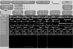
How about this one then? The signals I'm trying to generate are PC0 and Pin 16. I think I've worked out the others.

Inputs are CLK IN an SMPTE. It looks like Pin 19, 18 and 17 are CLK IN divided by 2, 4, and 8 respectively. Pin 15 is SMPTE offset by 1 CLK IN and Pin 14 is Pin 15 offset by 1 CLK IN.

CLK OUT is low when Pin 19 + Pin 18 + Pin 17 + possibly 16 are HIGH.
 

I've just managed to get something working with this second pal (signals shown in post above) and am tweaking it now to check it recovers from illegal states like the original etc.

This one was much more difficult and was exacerbated by the fact that my logic analyser seems to be pulling the circuit down and so it won't work properly with the analyser attached.
The simulator in Palasm showed the results I expected and I was getting the correct things while using test vectors on the device out of circuit, but in circuit it wasn't working (with the analyser attached). With the analyser attached there are missing signals.

I'm not sure if it really is the analyser causing this, there could be timing issues? so I have ordered some higher speed PALCE16V8. The PALCE16V8 I am using identifies/programs as a 'Q' (quarter power) device even though the part number I have is 'H' (which I think is half power).

Anyone got any thoughts on this, Is it possible that the new replacement device is not supplying enough current?

I will have to see what I can gauge with my O'Scope.
 

This thread is turning into a blog of just me talking to myself :)
Yesterday while testing out of circuit with my Boardmaster I found two sneaky illegal states that my PALCE substitute wouldn't recover from. The simulator in PALASM wasn't able to duplicate this. I made a few changes to my code.

The problem I had with my logic analyser was caused by the clock probe. If I probed the clock source for the PAL (which is an NMOS R6501) it worked fine, but with my PALCE substitute in there the clocks from the R6501 are inconsistent for some reason, probably a clash of logic tech.

This most likely had been making it much harder for me to test my design as I was probably looking at incorrect data with my analyser whereas the PALASM simulator showed it working fine of course.

I found two unused inverters on the pcb and cut the clock trace and then routed it through the inverters before sending it to the PALCE. Today I was able to get nice valid data in my analyser and found that the PALCE is doing exactly the same things as the original PAL device.

2 down, 1 to go.
 

Status
Not open for further replies.

Part and Inventory Search

Welcome to EDABoard.com

Sponsor

Back
Top