Continue to Site

Welcome to EDAboard.com

Welcome to our site! EDAboard.com is an international Electronics Discussion Forum focused on EDA software, circuits, schematics, books, theory, papers, asic, pld, 8051, DSP, Network, RF, Analog Design, PCB, Service Manuals... and a whole lot more! To participate you need to register. Registration is free. Click here to register now.

Programming Atmega128 with ISP problem

Status
Not open for further replies.
Any thoughts on this last question of mine?

Thanks for all of the help by the way!

J
 

I never saw your previous post, sorry.
A 2.2k resistor would draw about 2mA from the output so 30mA for all 15 outputs, that is correct.
About the leds, i don;t know the forward voltage of your leds but to calculate the current you do
resistor=(5v-Vforward)/current or current=(5v-Vforward)/resistor
for example a green led is about 2.2v so 5v-2.2v=2.8v/1000=2.8mA this seems to be very low, you probably need about 10mA,
a resistor about 220-270 ohm is usually used, it depends on the Vf and rated current of the led.
I don't see the leds on your schematic, there are only a couple of leds connected to the pic.

I'm not sure about the R21 resistor, you have to do some testing but i think it would work, it also depends on the programmer driving capability,
using the jumper would work for sure.

Alex
 
OK. Thanks for the info Alex. I am using this **broken link removed** with one color per transistor. The ES500RGB2 RGB model (last one on the list). I will plug in the numbers and see where I am at as soon as I get a minute to sit down.
 

The ISP header is completely BAD afaik. And if You plugged in the USB cable there, those two port could be burned.
 

The ISP header is completely BAD afaik. And if You plugged in the USB cable there, those two port could be burned.

That USB port is for a custom usb programmer. Not for a computer usb to be plugged directly into.
 

Yeah, this is just a prototype version that only myself and my programmer are using. The next version will have a different port.
 

How many leds do you use, it says that the strand can be cut every 3 leds, is that what you are doing?
The schematic is not clear in the datasheet but a see that the three leds (RGB) are connected in series with a resistor.
I don't see a way to control the 3 color leds individually, all 3 light together so i don't understand how you will use this as RGB from 3 transistor outputs.
About the resistors i thought that you meant the led resistor but you meant the one connected to the base of the transistors,
with the 2.2k you will be able to get an amp so this will be more than enough, you will be using less anyway.

Alex
 
Last edited:

Hi Alex. Thanks for your continued help! That is exactly what I needed to know about the transistor base resistors. I may add a jumper to R21 so that we don't have to worry about it.

The LED strands we will use are 18" (46 cm) to 24" (61 cm) long. The have four wires each. One for each color and one that is +12v. We control the colors individually by only applying power to the color that we need. We have been doing this for some time now on our first version so I know that it works. We have a total of 39 transistors (one per color) which gives us a total of 13 RGB strands. Each of these RGB strands will be controlled by PWM programming for infinite color mixing. The color mixing is a new feature we are adding and the main reason for the redesign. My first version used multi-plexors and we couldn't get the PWM programming to work.
 

Ok, the datasheet says max 72W consumption for 5m of ES500RGB2 which gives 14.4W/ meter so this is 14.4W/12v about 1.2A per meter
so you are using a max of about 0.72A for 60cm, i assume 1/3 of that for each color (and transistor) so about 0.72/3=0.24A.
Depending on the duration that these leds will be on you have to consider if you will be OK with the heat on the transistor,
as you provide more current the Vce saturation voltage (voltage drop) will lower but it will be worse for the AVR outputs.
Depending on the PCB pads this max power consumption on the transistor can be
390mW Device mounted on an FR4PCB, single-sided copper, tin-plated and standard footprint.
660mW Device mounted on an FR4PCB, single-sided copper, tin-plated, mounting pad for collector 1cm².

If you calculate using the 0.39W/0.24A=1.625v , above that you may have problems.
The datasheet specifies the Vce starting from a base current of 5mA (fig6 page 7 ), in that case the Vce=0.1v @25 Celsius for 0.24A, it will be a little more at higher temperature,
using the 2.2k resistors it will be higher but is should be about 0.3v so i think you are ok.

Alex
 
Ok. I am going to have to take some time and digest what you just wrote! I am a hobbyist at best so i have never had any training in the mathematics of it all so this is great information. I had already figured out the amps per strand, but as far as the rest, I would not have known where to start. Thanks for the info!

These will just be flashed momentarily. This is a lighting system for electronic drums so there will be no long durations of ON time. I don't think that heat will be a problem, but you never know on a song that uses a lot of one drum.
 

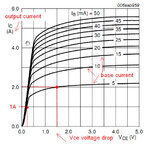
You will usually find a graph like the one below in every datasheet,
the curved lines represent different base currents,
the y axis on the left is the output current
and the x axis represents the voltage drop between collector-emitter.

You can calculate the power consumed on the transistor using this graph,
for example with a base current of 5mA and an output current of 2A(y axis) you can see that the voltage drop on the transistor will be 1.5v (x axis),
using that you can calculate 2A*1.5v=3W as heat

for 1A output and a base current of 5mA (at this current the curve is almost the same for different base currents) you have a voltage drop Vce=0.25v so 1A*0.25v=0.25W

this data changes with temperature and sometimes there are 2 graphs in different temperatures.
When the base current is higher you can get the same output current with lower voltage drop on the transistor between the collector and emitter.

Vce_saturation.jpg

Alex
 

Status
Not open for further replies.

Similar threads

Part and Inventory Search

Welcome to EDABoard.com

Sponsor

Back
Top