Vermes
Advanced Member level 4

- Joined
- Aug 2, 2011
- Messages
- 1,163
- Helped
- 0
- Reputation
- 0
- Reaction score
- 0
- Trophy points
- 1,316
- Activity points
- 22,318

Programmer presented in this article allows:
- uploading and downloading the content of single-circuit microcontrollers Atmel AT89CX051
- uploading and downloading the content of EEPROM I2C AT24C02
- communication with slave 1-wire devices
- generating the clock signal for Atmel, listing and download of ports values (something similar to the debugger interface)
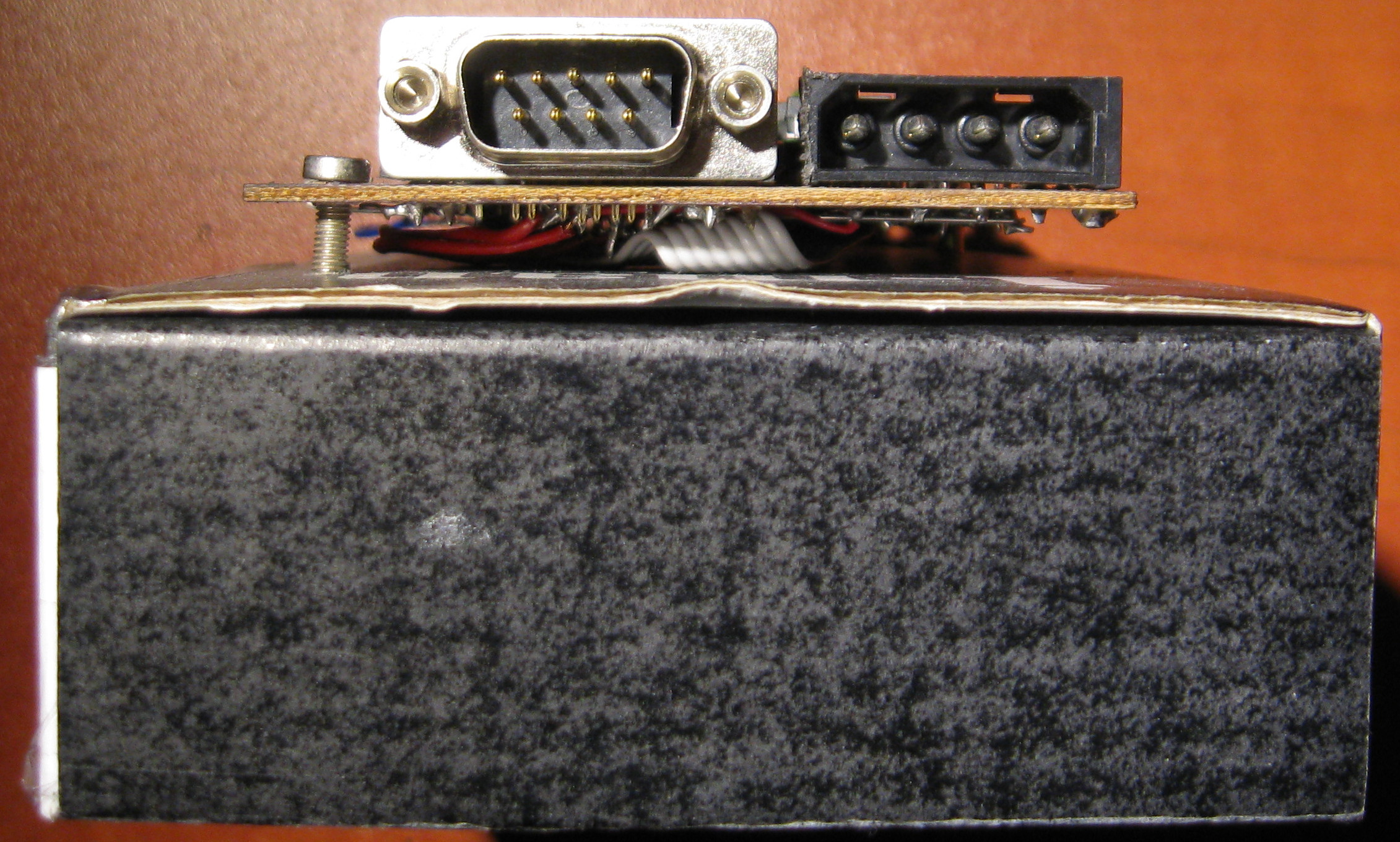
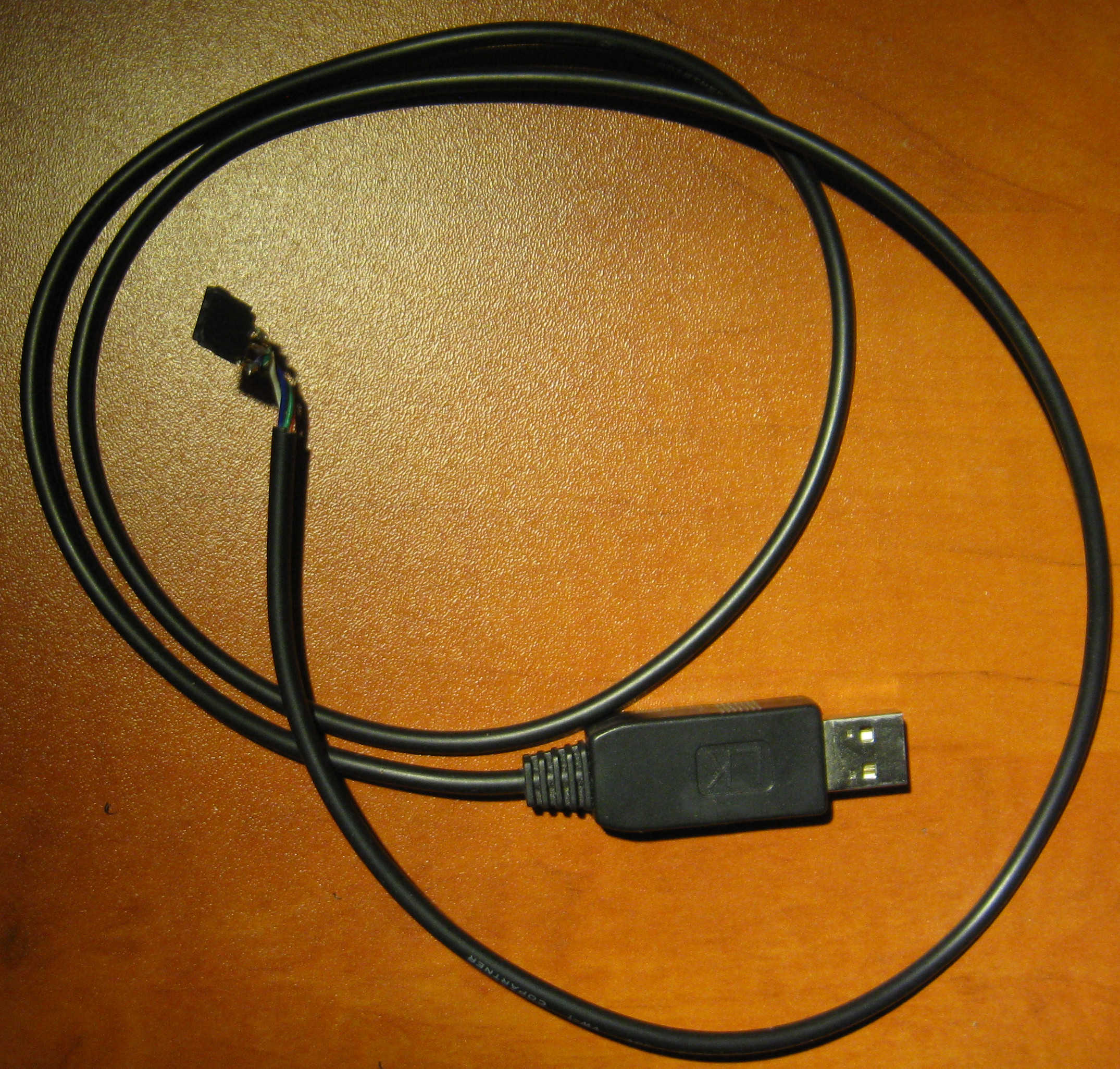
The programmer is equipped with a serial interface RS-232 (on MA232), and also has an UART connector, what allows you to connect it to the USB port. In this construction, USB cable Nokia type CA-42 is used (it works on chip ArkMicro 3116) with modified end that fits the UART connector.
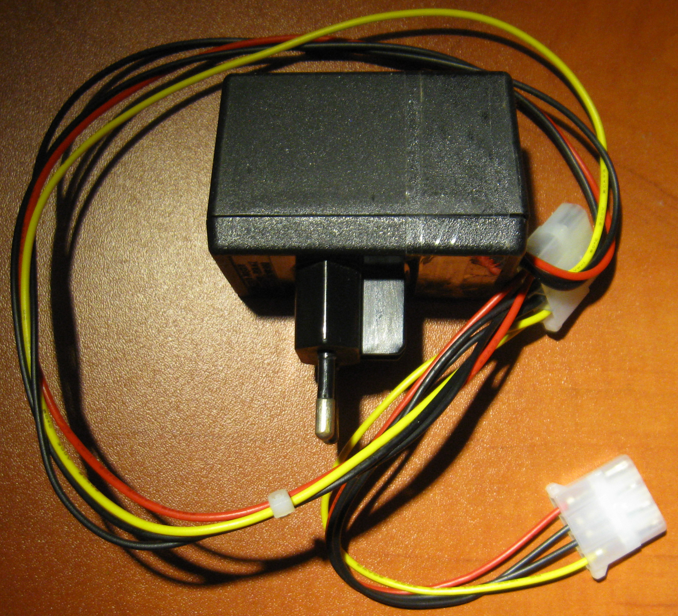
The programmer is powered from 5V and 12V, it has the power socket Molex. It is powered from a simple transformer power supply with a rectifier on Graetz bridge and stabilizers 7805 and 7812.
The programmer is based on microcontroller DS89C430 and is “self-programmable” (firmware for the main microcontroller can be uploaded in mounted circuit).
One of the firmware's features is that the interface from the computer is compatible with ISP interface of DS89C420. In other words, this programmer allows you to upload firmware to microcontrollers AT89CX051 (without ISP, they are only equipped with parallel programming protocol) in the same way (using the same tools) as in microcontrollers DS89C4X0 which are equipped with ISP.
Note that this programmer work was not tested with original program Dallas Semiconductor Microcontroller ToolKit for Windows, but with opensource equivalent for Linux (dsmtk). The interface is described in chapter 15 – Ultra-High-Speed Flash Microcontroller User's Guide (USER GUIDE 4833). It is the interface of text commands, and the memory content is sent in the format of Intel Hex.
In this implementation there are some differences, though. There is no function of automatic adjustment of baudrate. Instead of that, speed of 57600 bods is always used.
The list of commands slightly differs from the original one:
- W <port> <bajt_hex> (W <port> <byte_hex>) - providing a given value of byte to a certain port of the control microcontroller.
Possible ports: P0, P1, P2, P3.
Example: W P0 FF - R <port> – downloading the port value. It reads the value from the given port of the control microcontroller.
Possible ports: P0, P1, P2, P3.
Example: R P0 - L – loading the program to the Atmel Flash memory with verification (recommended).
For this command, there is a wrapper in dsmtk: /load, allowing to upload the hex file from the disk. - LB – loading the program to the Atmel Flash memory without verification (not recommended).
For this command, there is a wrapper in dsmtk: /load_blind, allowing to upload the hex file from the disk. - V – verification of the content of Atmel Flash memory.
For this command, there is a wrapper in dsmtk: /verify, allowing to upload the hex file from the disk. - D <adres_początku> <adres_końca> (<start_address> <end_address>) - Atmel Flash memory download.
Addresses are 16-bit words. <end_address> is the address of first byte that is not downloaded.
Example: D 0000 0800 - DS <adres_początku> <adres_końca> (<start_address> <end_address>) - signature download.
Example: DS 0000 0020 - K – deleting Atmel Flash memory
- LX – loading the memory I2C EEPROM (AT24C02)
For this command, there is a wrapper in dsmtk: /load_extern, allowing to upload the hex file from the disk. - DX <adres_początku> <adres_końca> (<start_address> <end_address>) - EEPROM download.
Older address bytes are ignored.
Example: DX 0000 00FF - G – handling of clock signal generator for Atmel
- G – switch off the clock signal
- G <słowo_hex> (<word_hex) – switch on the clock signal. It is the initial value of the 16-bit timer, after overload of which the state of line XTAL1 of Atmel will be changed
- G_ (_ is the coma) – display the current state of the timer
- A – display the current address of Atmel programming.
<word_hex> is displayed with the current address of Atmel programming. The programmer creates a mirror of that inner Atmel counter. - M <bajt_hex> (<byte_hex) – set the value of the top byte of 16-bit Atmel address counter, at which the counter turns to zero.
By default this value is 16 – the counter turns to zero at 4KB. For AT89C2051 with 2KB, it would be enough for 8. However, too big value will only cause the programmer turns the address counter to zero unnecessary more than it is required to zero it. - 1WR – reset the 1-wire bus
- 1W – communication with 1-wire bus
- 1W <ciąg_bajtów_hex> (hex_byte_string) – sending a byte string to the bus
- 1W – read the bytes from the bus
Example – temperature read from DS18B20:
1WR
1W CC44
1WR
1W CCBE
1W
1W
Firmware translates these commands respectively to:
- parallel software protocol AT89CX051, described in AT89C2051 Complete (doc0368) – for L, LB, V, D, DS, K
- programming AT24C02 by I2C protocol, described in Interfacing AT24CXX Serial EEPROMs with AT89CX051 MCU (doc0507) – for LX, DX
- 1-wire protocol – for 1WR, 1W
Schematic of the programmer:
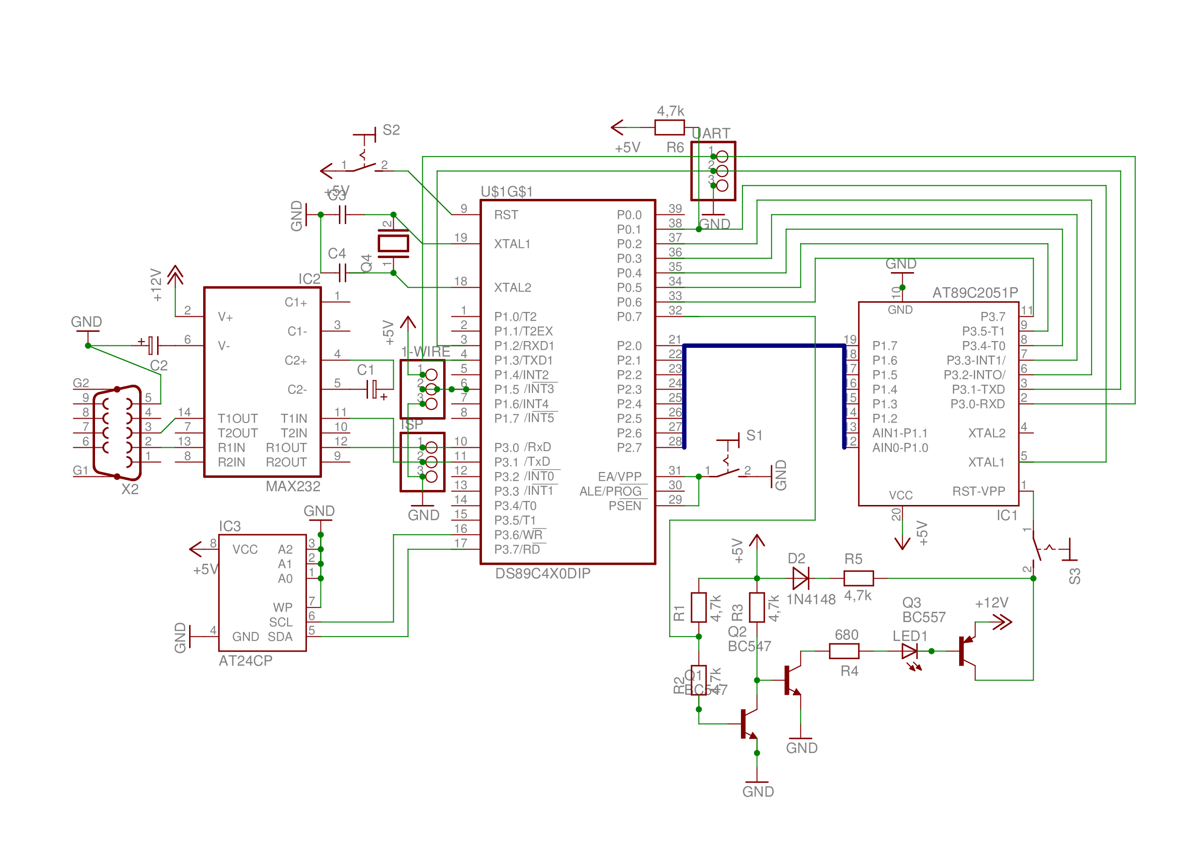

Remember to add a capacitor 1uF between RST DS89C430 and VCC (it was not marked on the schematic).
LED indicates the presence of 12V on pin RST/VPP of Atmel.
The programmer has three switches:
- S2: RESET DS
- S1: PROG DS
- S3: PROG AT
Entry into the mode of programming the main processor (ISP) includes switching on RESET DS and PROG DS before connecting the power.
1-wire and EEPROM I2C handling is possible when all the switches are on, as well as the PROG AT.
Programming (and downloading memory) of AT89CX051 is possible when the PROG AT is on. It switches the control by Atmel reset from the main processor (switching between 5V and 12V).
When PROG AT is on, Atmel can work normally.
Link to original thread (useful attachment) - Programator AT89CX051 i AT24C02 + 1-wire na RS-232 i USB