Continue to Site

Welcome to EDAboard.com

Welcome to our site! EDAboard.com is an international Electronics Discussion Forum focused on EDA software, circuits, schematics, books, theory, papers, asic, pld, 8051, DSP, Network, RF, Analog Design, PCB, Service Manuals... and a whole lot more! To participate you need to register. Registration is free. Click here to register now.

Problems with lm2576

Status
Not open for further replies.

noirs

Newbie level 1
Newbie level 1
Joined
May 9, 2013
Messages
1
Helped
0
Reputation
0
Reaction score
0
Trophy points
1,281
Visit site
Activity points
1,288
Hello!

I'm trying to make an adjustable lm2576 circuit where I can change the output with a pic and two transistors. But when I try it in real life it doesn't regulate the current. When I use 24 V on the input it just goes through and I get 22,4 V on output when I should have 12 V.
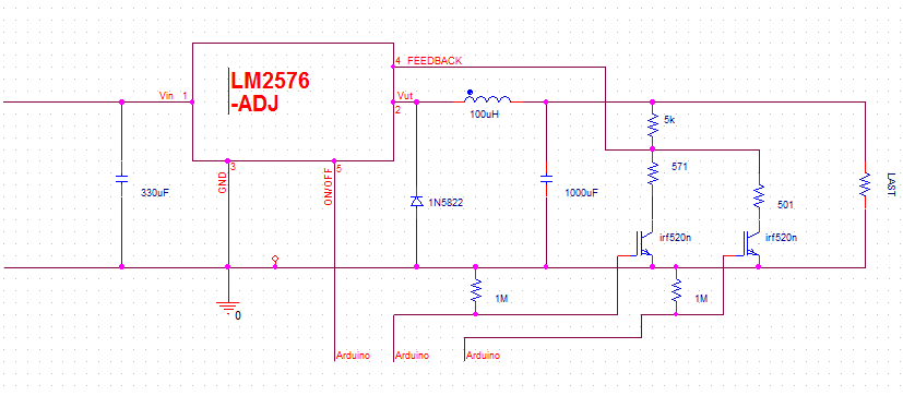
lm2576-adj2.png
 

If both FETs are on Vo=1.23 (1+R2/R1) where R2=5k and you have two FETs + R1s , 571 and 501 ( both // = 267R )

1) 1.23 (1+5k/571) =12.0V
2) 1.23 (1+5k/267) = 24.2V err.

Is it possible both FETS are active? What is Vfeedback?
 
  • Like
Reactions: IanP

    IanP

    Points: 2
    Helpful Answer Positive Rating
Hello!

I'm trying to make an adjustable lm2576 circuit where I can change the output with a pic and two transistors. But when I try it in real life it doesn't regulate the current. When I use 24 V on the input it just goes through and I get 22,4 V on output when I should have 12 V.

Try this circuit as if it were a stand-alone unit, see attached picture ...
Once you're satisfied, connect it to Arduino.
:wink:
IanP
 

Attachments

  • lm2576-adj2_arduino2.PNG
    lm2576-adj2_arduino2.PNG
    15.6 KB · Views: 119

Status
Not open for further replies.

Similar threads

Part and Inventory Search

Welcome to EDABoard.com

Sponsor

Back
Top