Continue to Site

Welcome to EDAboard.com

Welcome to our site! EDAboard.com is an international Electronics Discussion Forum focused on EDA software, circuits, schematics, books, theory, papers, asic, pld, 8051, DSP, Network, RF, Analog Design, PCB, Service Manuals... and a whole lot more! To participate you need to register. Registration is free. Click here to register now.

Problems with a 1-bit memory circuit I've been trying to replicate.

Status
Not open for further replies.

automaton_be

Newbie level 2
Newbie level 2
Joined
Sep 5, 2013
Messages
2
Helped
0
Reputation
0
Reaction score
0
Trophy points
1
Visit site
Activity points
22
Someone at the hackerspace I regularly visit, built this 1-bit memory circuit, and drew this schematic of it:
schematic-01.png
The idea is, that on set/reset, one or the other led comes on and stays on as long as the circuit is powered.

I've been trying to get this circuit to work, but to no avail. When I assemble the components on a breadbord, both leds illuminate dimly, and setting/resetting only momentarily makes one or the other brighter.
At this point, I'm trying to figure out whether the circuit design makes sense, before I start looking for broken components or an error on the breadboard.
So, if someone could just check this diagram for errors, that'd be awesome.
 

Attachments

  • IMG_2801.JPG
    IMG_2801.JPG
    2.4 MB · Views: 109

I guess the way this is SUPPOSED to work is that when you close a switch, the associated transistor is turned off, and the other transistor is turned on. For example: if Sset is closed, the left Q is turned off and the right Q is turned on (supposedly) by the current through R0,D0, and R1. I'm not sure there's enough current to do that. I'd try making R1 and R2 smaller, maybe 1K.
 

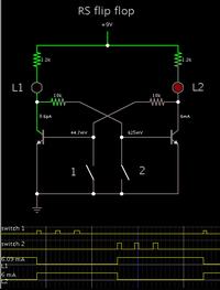
Here is a simulation. I used the values in your photograph.


The last action was to close switch #1 momentarily.

Your description suggests your transistors are never fully turning on or off. You will need to verify each one's operation, individually.
 

It was very clear one transistor shd make other off by giving a low input, the problem is because your practical transistors has high gain (hfe) to ON from a low input current,

so increase the 1k to 1.5k and 20k to 33k.. It has to work if both LEDs remain OFF try reducing according to your transistor gain....
 

That's some great debugging advice, thanks! So, just to be clear, the circuit itself isn't riddled with errors?
Also, @Bradtherad, I suppose the simulation software you're using is of the really expensive professional variety?
 

Also, @Bradtherad, I suppose the simulation software you're using is of the really expensive professional variety?

It is Falstad's interactive animated simulator. You'll be happy to hear it is free to download and use...

www.falstad.com/circuit

Or else you can click this link. It will open Falstad's website, load my schematic above, and run it on your computer.

https://tinyurl.com/mlevabb

Click the switches to operate the flip-flop.

It portrays led's lighting, and current bundles flowing in the wires at proportional speed.
 

I've been trying to get this circuit to work, but to no avail.
The circuit diagram looks OK. My guess is you'vegot one (or both) of the transistors connected the wrong way around, probably with the collecter and emitter connections swapped.
 

Zooming in on your photograph, I wonder which three rows your left-hand transistor contacts?

From what I can see, the lead going into F5 is very short.
And G5 looks as though it is occupied by a jumper.

So do I deduce correctly that the other two transistor leads are in row 4? If so then this means they are shorted to each other.
 

Status
Not open for further replies.

Part and Inventory Search

Welcome to EDABoard.com

Sponsor

Back
Top