Continue to Site

Welcome to EDAboard.com

Welcome to our site! EDAboard.com is an international Electronics Discussion Forum focused on EDA software, circuits, schematics, books, theory, papers, asic, pld, 8051, DSP, Network, RF, Analog Design, PCB, Service Manuals... and a whole lot more! To participate you need to register. Registration is free. Click here to register now.

problems faced during adc execution in atmega16

Status
Not open for further replies.

southpaw4471092

Junior Member level 1
Joined
Apr 6, 2012
Messages
15
Helped
0
Reputation
0
Reaction score
0
Trophy points
1,281
Visit site
Activity points
1,392
Hi,
im having a problem in executing the in-built adc function practically.Please help me rectify it.
i will elaborate on my doubts.Initially how should the AVCC ,AVref pin connected?
Also i have another problem with the execution of IF statement, evn when condition becomes false, it executes the statement inside if condition.
the following is my code.
Code:
void adc_init()
{
	ADMUX|=(1<<REFS0)|(1<<REFS1);
	ADCSRA|=(1<<ADEN)|(1<<ADPS1)|(1<<ADPS0)|(1<<ADPS2);
}
uint16_t adc_read(uint8_t ch)
{
	// select the corresponding channel 0~7
	// ANDing with '7' will always keep the value
	// of 'ch' between 0 and 7
	ch &= 0b00000111;  // AND operation with 7
	ADMUX = (ADMUX & 0xF8)|ch;     // clears the bottom 3 bits before ORing
	
	// start single conversion
	// write '1' to ADSC
	ADCSRA |= (1<<ADSC);
	
	// wait for conversion to complete
	// ADSC becomes '0' again
	// till then, run loop continuously
	while(ADCSRA & (1<<ADSC));
	
	return (ADCW);
}
void main()
{
DDRB|=(1<<PB0);
adc_init();
while(1)
{
if(adc_read(0) > 400)
{
PORTB|=(1<<PB0);
}
}
}
 
Last edited by a moderator:

Hi jayanth,
thanks alot. MY activity is to interface an analog ir senor to atmega 16 using adc which is the first part of building a line follower. so the range is 0-5 Volts.
 

Have you interfaced analog IR sensor to adc pin? What voltage are you getting at adc input pin? If your sensor output is 0v to +5V then you can use ARef of 5V. Post your interface circuit and also the link for your IR sensor datasheet.
 

ya i have interfaced it. so Aref should be connected to 5v.
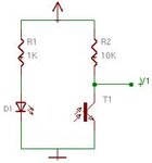
photo.jpg
Another problem i face is about the IF statement i have posted above please do tell me about it.

- - - Updated - - -

To say in short, even when the IF condition fails it keeps on executing thta is the output gets retained.
 

Your circuit is a digital IR circuit. It doesn't give any analog output. It is a switching circuit which gives high or low pulses depending upon the IR burst signal. This will not give you adc value.

How do you know that if condition is failing? Give dc 4V to analog adc input and see the output.
 

how can yo say it as a digital ir circuit?? Only if i connect it to a comparator it will give binary values. Actually i couldnt figure out the problem with IF statement. After numerous failures, i could understand only this. IF my condition is true led should glow,if not it should be off. But in my case whether the condition is true or false led keeps glowing. do help me find where the fault is.
 

See in your interfacing circuit. When IR detector detects pulse (switches ON) V1 the output of circuit is 0V else it will be at +5V if you give 5V to the circuit. So, adc input will be always +5V so led will always light ON. IR signal is 38 KHz. Even if you send IR signal then your adc input fluctuates between 0V and 5V in some pattern like say 10101010 at 38 KHz.
 

Its not like that,depending on the colour the output varies.Practically, when i use black it gives 0v and white it gives 4v but while using white the output also varies according to the distance.Tell me something about the IF statement problem...

- - - Updated - - -

Give me the syntax for checking 2 port pins as high and if its high led should glow else it should not..
 

if adc value is > 400 then led will be ON. What IR transmitter and detector are you using? Can you explain how Vout at collector of photo detector varies with analog values?

- - - Updated - - -

What do you mean by syntax?
 

if i use white, if i place at x cm i get different output and if i place at y cm (x>y) i get different output .This is what i say analog values. Syntax in c programming. Could yo provide me any code for line follower? Actually im in urgent need of it.


Code:
	while(1)
	{
		a0 = adc_read(0);      // read adc value at PA0
		a1 = adc_read(1);      // read adc value at PA1
		a2 = adc_read(2);
		a3 = adc_read(3);
		a4 = adc_read(4);


		// now display on lcd
		itoa(a0, int_buffer, 10);
		lcd_gotoxy(6,0);
		lcd_puts(int_buffer);
		
		itoa(a1, int_buffer, 10);
		lcd_gotoxy(6,1);
		lcd_puts(int_buffer);
		_delay_ms(5);
		/*itoa(a2, int_buffer, 10);
		lcd_gotoxy(6,0);
		lcd_puts(int_buffer);
		_delay_ms(5);
		itoa(a3, int_buffer, 10);
		lcd_gotoxy(6,1);
		lcd_puts(int_buffer);
		_delay_ms(5);
		itoa(a4, int_buffer, 10);
		lcd_gotoxy(6,0);
		lcd_puts(int_buffer);
		_delay_ms(5);*/
		if(a1 > 500 & a2 > 500 & a3 > 500)
		{
			PORTC|=(1<<PINC1);PORTC&=~(1<<PINC0);
			PORTC|=(1<<PINC3);PORTC&=~(1<<PINC2);
			_delay_ms(2);
			break;
		}else if(a0 > 500 & a1 > 500 & a2 > 500)
		{
			PORTC|=(1<<PINC0);PORTC&=~(1<<PINC1);
			PORTC&=~(1<<PINC2);PORTC&=~(1<<PINC3);
			_delay_ms(2);
			break;
		}
	}
}

in the above code, in the IF statementif any of the a0,a1,a2 is false it shoud not execute the corresponding statement. but the problem i face is if condition true it executes ,even if its false it does not change its state. Please comment on this.
 
Last edited by a moderator:

You have to use if...elseif condition to check adc values like if adcval > 100 then do something elseif adcval > 200 then do some other thing. like that. Can you tell what sensor you are using?

Your code is wrong. You should use && instead of &.
 

I am using an IR transmitter and a Phototransistor. I had problems with my previous controller so a bought a new one. To test whether all the pins are working, i declared all ports to be output and gave PortX=0,all pins showed 0 except 3 pins in the PORTD. Also AVCC and Aref pins are high eventhiough they are not hardwired to VCC. Does that mean my controller is defective??
 

Status
Not open for further replies.

Similar threads

Part and Inventory Search

Welcome to EDABoard.com

Sponsor

Back
Top