Continue to Site

Welcome to EDAboard.com

Welcome to our site! EDAboard.com is an international Electronics Discussion Forum focused on EDA software, circuits, schematics, books, theory, papers, asic, pld, 8051, DSP, Network, RF, Analog Design, PCB, Service Manuals... and a whole lot more! To participate you need to register. Registration is free. Click here to register now.

Problem with Phase Firing Angle in dimmer circuit

Status
Not open for further replies.

Don_dody

Full Member level 1
Full Member level 1
Joined
Nov 4, 2012
Messages
96
Helped
1
Reputation
2
Reaction score
1
Trophy points
1,288
Location
Indonesia
Visit site
Activity points
1,921
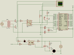
The circuit that I've built:

ZCD.png

The code:

Code:
#include <mega8535.h>
#include <delay.h>

// External Interrupt 0 service routine
interrupt [EXT_INT0] void ext_int0_isr(void)
{
    PORTB=0x00;
    delay_ms(5);  // firing triac 6 ms after zero cross detected
    PORTB=0x01;   
    delay_us(1);  // firing pulse width 1 us
    PORTB=0x00;
}

void main(void)
{

PORTB=0x00;
DDRB=0x01;        // PORTB.0 as output

GICR|=0x40;       // INT0
MCUCR=0x01;
MCUCSR=0x00;
GIFR=0x40;

// Global enable interrupts
#asm("sei")

while (1)
      {
      }
}

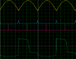
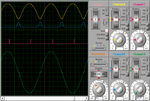
The simulation result:

OSC.png

My questions:

1. Is my code right?
2. What's wrong with green wave in the oscilloscope? Why I didn't get something like this :
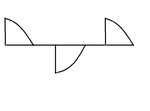
Res.png
 
Last edited:

Not quite sure how U5 is supposed to work, but the signal on R9 is low 99.99999% of the time, which means the opto is on. Maybe that should be inverted.
 

The mains neutral line is near earth potential, you are monitoring the voltage on the gate which is referenced to the mains live. So you have to subtract the mains sine wave from your green display for it to mean any thing, or put a probe on the ac live and show the green display as the differential voltage.
Frank
 

Though it not related to the query asked in this thread I would like to suggest to use timer instead of using delay.
 

How? can you give more explanation?
which part of my code should be modified?

enable a timer inside the ext int function to start counting time. When timer overflow occurs set output PORTB=0x01;
Code:
ISR ()
{
check Ext Int flag
{
enable timer
}

Check timer overflow flag
{
set output like PORTB=0x01;
}
} 
 
main()
{
}
 

Hi,

I've re-build the code and now I'm using timer.
This is it:


Code:
#include <mega8535.h>
#include <delay.h>

// External Interrupt 0 service routine
interrupt [EXT_INT0] void ext_int0_isr(void)
{
    PORTD.0 = 0;              //initially triac off
    TCCR1B = 0x02;
}

// Timer1 output compare A interrupt service routine
interrupt [TIM1_COMPA] void timer1_compa_isr(void)
{
    TCNT1H=0x00;
    TCNT1L=0x00;
    PORTD.0 = 1;
    delay_us(100);
    PORTD.0 = 0;
    TCCR1B=0x00;
}


// Declare your global variables here

void main(void)
{

PORTD=0x00;
DDRD=0x01;


// Timer/Counter 1 initialization
// Clock source: System Clock
// Clock value: 1500.000 kHz
// Mode: Normal top=0xFFFF
// OC1A output: Discon.
// OC1B output: Discon.
// Noise Canceler: Off
// Input Capture on Falling Edge
// Timer1 Overflow Interrupt: Off
// Input Capture Interrupt: Off
// Compare A Match Interrupt: On
// Compare B Match Interrupt: Off
TCCR1A=0x00;
TCCR1B=0x02;
TCNT1H=0x00;
TCNT1L=0x00;
ICR1H=0x00;
ICR1L=0x00;
OCR1AH=0x1D;                  // 5ms prescaller:8, crystal;12MHz  ==>(5/1000)*(12000000/8)=7500 in hex 1D4C
OCR1AL=0x4C;
OCR1BH=0x00;
OCR1BL=0x00;

// External Interrupt(s) initialization
// INT0: On
// INT0 Mode: Falling Edge
// INT1: Off
// INT2: Off
GICR|=0x40;
MCUCR=0x02;
MCUCSR=0x00;
GIFR=0x40;

// Timer(s)/Counter(s) Interrupt(s) initialization
TIMSK=0x10;

// Analog Comparator Input Capture by Timer/Counter 1: Off
ACSR=0x80;
SFIOR=0x00;


// Global enable interrupts
#asm("sei")


while (1)
      {
      // Place your code here

      }
}

Now I get a smooth wave (as shown by the green wave) and it never change even I trigger the triac 5ms after the zero cross.
Wave.png

I've change the dimming circuit too. It look like this:
Dimmer Circuit.png

Please tell me the mistake that made either the code or the circuit. I really don't know what to do now.
 

Why don't you show us what the OUTPUT looks like? Your 'green wave' is the trigger for the TRIAC, and it looks like it turns on at about 5 degrees, we have no idea what the other waveforms are. What do you THINK your problem is?
 

Oh wait, if I want to see the output from oscilloscope, where should I connect the probe?
Maybe this is the problem.

On that picture, the yellow wave is rectifier output. Blue= zero crossing. Red=Triac triggerring pulse. Green= this is it, I though this is the output.
 
Last edited:

You will get load waveform from MT1 of TRIAC. (connect osc probe at MT1 of TRIAC)
 

Status
Not open for further replies.

Part and Inventory Search

Welcome to EDABoard.com

Sponsor

Back
Top