Continue to Site

Welcome to EDAboard.com

Welcome to our site! EDAboard.com is an international Electronics Discussion Forum focused on EDA software, circuits, schematics, books, theory, papers, asic, pld, 8051, DSP, Network, RF, Analog Design, PCB, Service Manuals... and a whole lot more! To participate you need to register. Registration is free. Click here to register now.

Problem with Phase Difference

Status
Not open for further replies.

Monady

Advanced Member level 4
Full Member level 1
Joined
Dec 1, 2008
Messages
109
Helped
12
Reputation
24
Reaction score
3
Trophy points
1,298
Activity points
2,151
Hi dear all friends,
I have a problem with Hspice that may make you laugh! I simulated very very simple RC circuit! The value of capacitor and resistor are 0.01pF and 10KΩ, respectively. And input signal is a sine wave with 10MHz frequency. We can say that, based on the value of elements, this circuit is almost a pure resistive circuit. So we expect to have 0 degree phase difference. Also, based on the formula of phase difference, which is invtan(-Xc/R), the phase difference of this circuit should be 179.3 degree. Now I get confused why Hspice shows 90 degree phase difference (please take a look at the attached pic).
I would appreciate any help.
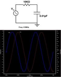
 

You should first specify for which quantities you want to determine a phase difference. There are many possibilities. Mostly, one would look at output to input voltage.

Your simulation however displays phase difference between (input) voltage and current, which is a different thing. It's defined by the phase of the series impedance, which is dominated by the capacitor in this case, resulting in a 90° phase.

P.S.: You also should reconsider this statement. You'll hardly find a near to 180° phase difference in a RC circuit. It's also not clear to me, which phase difference would be described by the formula.
Also, based on the formula of phase difference, which is invtan(-Xc/R), the phase difference of this circuit should be 179.3 degree
 
Last edited:

Tnx for your reply dear FvN.
You should first specify for which quantities you want to determine a phase difference.
I wrote that the value of capacitor and resistor are 0.01pF and 10KΩ, respectively. And input signal is a sine wave with 10MHz frequency.
Your simulation however displays phase difference between (input) voltage and current, which is a different thing. It's defined by the phase of the series impedance, which is dominated by the capacitor in this case, resulting in a 90° phase.
Assume that we're going to find total power consumption of a circuit. We should use this formula: P=V*I*cos(φ), which φ is a phase difference between voltage and current of the input voltage source.
If the circuit is pure resistive, phase difference will be 0. If the circuit is pure capacitive , phase difference will be 90. And for an RC circuit, based on the values of elements, we have another phase difference.
what I'm saying is that, in our case,because the value of capacitor is very small compared to the resistor value, the circuit should behave like a pure resistive circuit, but I didn't. Now the question is why it didn't!
P.S.: You also should reconsider this statement. You'll hardly find a near to 180° phase difference in a RC circuit. It's also not clear to me, which phase difference would be described by the formula.
please take a look:
https://users.stlcc.edu/cburkhardt/sum/lab/rlc.pdf
**broken link removed**
 

because the value of capacitor is very small compared to the resistor value, the circuit should behave like a pure resistive circuit, but I didn't.
It's just the other way around. It behaves almost capacitive.

I see, that the formular is describing the phase angle of the RC series circuit's impedance, so it actually applies to the problem. But your calculation is wrong. You get an Xc of 1.6e6 and an angle of -89.6°, or about 90°, as in the simulation waveform.
 
  • Like
Reactions: Monady

    Monady

    Points: 2
    Helpful Answer Positive Rating
Yeah, this formula gives us the phase angle of the RC circuit impedance, say φ. But, since I=V/Z and phase of V and Z are 0 and Φ respectively, the phase of the current (I) would be -Φ. As a result, phase difference, <V-<I, would be 0-(-Φ)=Φ.
Please correct me if I made a mistake. I don't know why my calculation is wrong!
 

Status
Not open for further replies.

Similar threads

Part and Inventory Search

Welcome to EDABoard.com

Sponsor

Back
Top