Continue to Site

Welcome to EDAboard.com

Welcome to our site! EDAboard.com is an international Electronics Discussion Forum focused on EDA software, circuits, schematics, books, theory, papers, asic, pld, 8051, DSP, Network, RF, Analog Design, PCB, Service Manuals... and a whole lot more! To participate you need to register. Registration is free. Click here to register now.

problem with output from a demodulator(multiplier)

Status
Not open for further replies.

niloy2k

Junior Member level 1
Joined
Feb 17, 2009
Messages
18
Helped
0
Reputation
0
Reaction score
0
Trophy points
1,281
Activity points
1,442
what is meant is demodulation?

Hi guys I previously posted here asking for a help with the noise source and I really really appreciate the help from everyone.

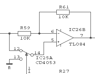
I am working on a project which is based on lock in amplification. Basically the main phase of the design is the phase sensitive detection where demodulation(multiplication) of two signals takes place.

For my project I have to extract a very weak signal buried in large noise. In the demodulator stage, the circuit works fine if i just multiply a simple sine wave and a square wave havin da same phase as it provides me fully rectified signal. But if I add the noise signal with the sine wave and then perform the demodulation step, the output does not turn out to be fully rectified signal.

I have tried lookin at all the specs but I cant figure out whats wrong with the procedure. Can anyone please please help me out with this ?? I will really appreaciate the help :)
 

am demodulator using only op amps

the output does not turn out to be fully rectified signal.
Can you please clarify this vague description, to make the problem understandable?

Generally, when using a square wave for demodulation, the input to the demodulator should be bandlimit below 3*fc, cause the demodulator is also sensitive for odd harmonics of the reference frequency.
 

what is a demodulated output

sorry about being vague ..... the thing is .... as i described earlier .... i wil have to build a circuit which wil extract very weak signal from noise which is atleast 10 times larger than the original signal

only using a low pass filter here wont give me the perfect result .... so firstly .... i send my original signal which i added wit the noise through a amplifyin stage first before being on the input to the demodulator

at the same time i use the same function generator which produced the sine wave to produce a square wave through a comparator circuit .... and put it as the second input to the demodulator

the demodulator will only multiply signals that are in phase ... and as such ... this is a better way of gettin rid of the maximum amount of noise that has overwhelmed my required .... i also have a phase shifter for the previously transformer square wave to make sure that the signals are in phase ... any signal out of the phase is instantly diminished .... and the output of the demodulator always produces a fully rectified signal (multiplication result of a sine wave and a square wave)

my problem is .... if the i multiply a clean sine wave and square wave .... i get proper output results .... but if i multiply a sine wave which is already buried in noise (noise collected from reverse biased zener .... amplified through a series of 741 op amps and added with a sine wave using a summing amplifier) the output is not fully rectified ... or rather it is half rectified .... i am not sure what is causing the problem

I hope this is detail enough for you and please if you still dont understand let me know and i will break it downn even more :) thanks a lot for the help
 

multipliers demodulate to dc

You mainly repeated your previous post verbosely, but you didn't tell, how the demodulated signal looks like. It would be also interesting to know, what's the exact demodulator circuit respectively it's operation principle, e. g. if it's DC free.

You may want to think about the said bandlimit issue later, possibly when you're doing quatitative SNR measurements, but it can be ignored for the time being.

As a reference, I want to show what I consider a typical square wave synchrone demodulator, without pre- or succeeding filters:

15_1235942613.gif
 

am square wave demodulator circuit

sorry about the reply again .... the output that i am gettin now is like a half rectified wave .... but i am supposed to get a fully rectified wave

as for the demodulator i am using a demodulator chip known as the AD734 .... i will attach the datasheet for ur convenience

would it be helpful if i sent u images of the simulation circuit i built on multisim electronic workbench - both with the noise and without the noise along with their display of the oscilloscope? this is a very crucial stage of my project and i wud really appreciate ur help ... i am sorry for being vague everytime and thanks a lot for the help so far :)

Added after 4 minutes:

heres the data sheet
 

demodulator na 4053

It's impossible to get a half wave demodulated signal instead of a full wave by adding some noise to the input. It should be clear however, that you don't add a large DC offset along with the noise or exceed the multiplier input range in any other way.
 

multiplying based phase sensitive demodulation

so u r sayin dat in no way i am supposed to get a half rectified wave even with the addition of noise and as such i might have some problem while providing the two signals to the demodulator ?
 

741 used as a synchronous demodulator

You should post the MultiSim files and/or show the schematics.
 

multisim demodulation

thanks a lot for the co operation so far .... i really appreciate it .... i will attach both the multisim files with and without noise in it ... please chek the output from the demodulator for both the cases .... please let me know the feedbacks ... and once again i really appreciate the help :)
 

In a short, the no-noise operation is faulty as well, cause the multiplier is completely overloaded. Furthermore, the circuit is missing a DC block (highpass) in the signal path. In the noise added circuit, the signal input seems to be mainly DC, resulting in square wave output, apparently also overloading the multiplier-

Without overload, the square wave component would be removed in the demodulator post filter, so it's not absolutely required to have a DC free input signal at the demodulator, but it's advisable for better performance and less resisual signals at the output.

I also don't understand the purpose of the notch filters at both multiplier inputs.

Rather than designing complex simulation circuits, I suggest to use simple principial circuits first, that are clear regarding DC and signal levels. Analog behavioral models as ideal multipliers or switches can be used at this design phase.
 

    niloy2k

    Points: 2
    Helpful Answer Positive Rating
thank u very much for the earlier response

I have modified the no noise circuit by reducing the input values of the demodulator .. n thus it is not overloaded now anymore ...although i am confused about what u meant about the circuit missin a high pass along the signal path

with the noise circuit ... i have removed the dc component by using a capacitor along the way ... but the results am gettin now is even more corrupted than before ... its almost producing the same noisy signal dat i am puttin in as the input

i used the notch filters to remove any main hum noise (for practical purpose) but i have removed it off from the simulation now .... i have attached the 2 new schematics now ....i wud really appreciate if u helpd me out ... thanks
 

I don't have the time now to inspect the new circuit, but I guess, I know the result anyway. Removing the DC component with a capacitor is just another word for a high-pass. So, that's one step forward. Without noise added, you should see a full-wave rectified sine without any clipping. I expect that it's O.K. by reducing the level.

With a large noise amount added, you basically see noise at the output. That's normal operation. It seems to me, that you didn't yet think thoroughly about synchronous demodulator operation principle. Viewn simplified, it just shifts the signal around the reference frequency to zero in frequency domain, but it doesn't yet filter any components. So the SNR isn't changed. The purpose of a synchronous demodulator reveals with a low-pass filter at the output. You can e.g. apply a 0.1 Hz low pass filter, so referred to the input, all frequency components except a small band around the reference frequeny are suppressed. The detected signal appears now as a DC value. Because noise power is proportional to bandwidth, you can't remove any noise with the low-pass, but reduce it considerably.

As previously mentioned, also the reference frequency odd harmonics pass the demodulator and detoriate the SNR, so you may want to filter them before entering the demodulator. In principle, a sine reference signal also suppresses them, but for various reasons, the performance is worse anyway.

That's, in a short, the SyncDemod operation principle. Think about it, read some literature and evaluate it in your example circuit.
 

    niloy2k

    Points: 2
    Helpful Answer Positive Rating
thank you so much for the reply earlier yesterday ... so i suppose u r askin me to use a basic synchronous demodulator circuit for the experiment .... u showed me a diagram earlier .... does that have the capability of multiplying a sine wave and a square wave ? and also the IC that u used (cd 4053) is mux/demux unit if i am not mistaken .... do i need to use that as wel ? thanks :)
 

The shown synchronous demodulator (basically a +/-1 switchable amplifier) is a good alternative to an analog multiplier, if you don't require a sine reference signal. Of course you can use different analog switches with a higher voltage range, if meaningful. Compared to a multiplier, the simple circuit has superior linearity and dynamic range.
 

basically my square wave is the refernce signal ... so in ur circuit i see one input branchin into the opamp .... i am a bit confused about that ... cud u help plz .... or in other words ... wud i provide both my signals in this circuit ?
 

The square wave is fed to the analog switch, with a suitable logic level.
 

Status
Not open for further replies.

Similar threads

Part and Inventory Search

Welcome to EDABoard.com

Sponsor

Back
Top