Continue to Site

Welcome to EDAboard.com

Welcome to our site! EDAboard.com is an international Electronics Discussion Forum focused on EDA software, circuits, schematics, books, theory, papers, asic, pld, 8051, DSP, Network, RF, Analog Design, PCB, Service Manuals... and a whole lot more! To participate you need to register. Registration is free. Click here to register now.

Problem with mixer output

Status
Not open for further replies.

mordak

Member level 5
Joined
Mar 8, 2013
Messages
82
Helped
0
Reputation
0
Reaction score
0
Trophy points
1,286
Location
Neverland
Activity points
2,134
Hey guys,

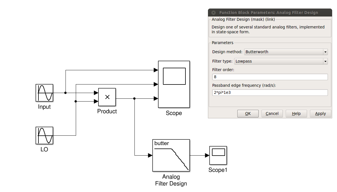
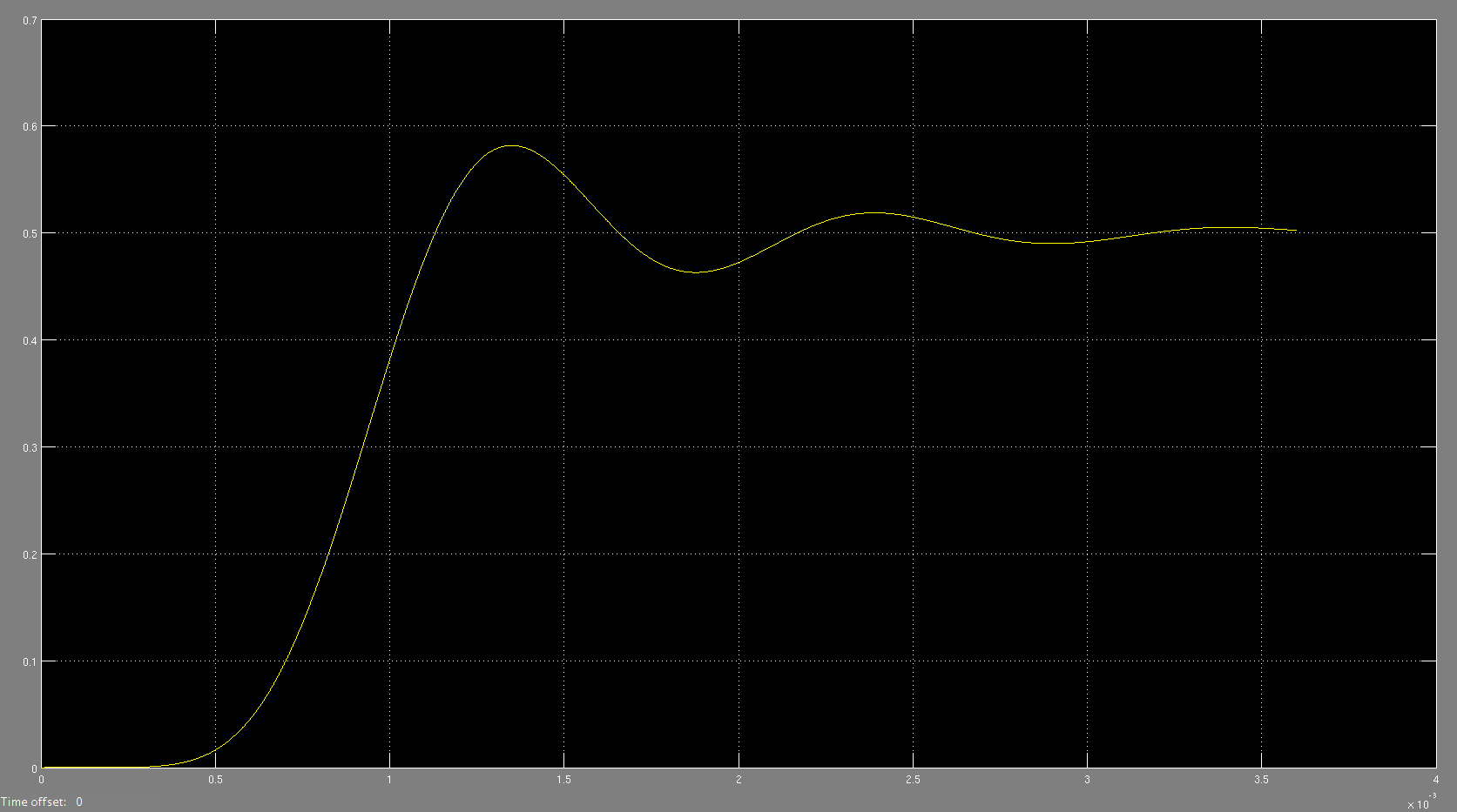
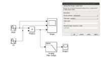
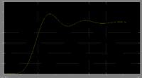
I have just started reading some stuff about mixers and tried to implement a down converter, but I tried to simulate a system level before getting to circuit design. But I got some results and at least to me they are not correct. Some snapshots of my design in Matlab are attached. frequency of both input and local oscialtor (LO) is 10kHz, so I expect to get output signal at 20kHz and DC. Then I added a low pass filter which its passband freq. edge is 1kHz, however, output of the filter is not what I expected. I assume that 2*pi*1kHz would be the cut off frequency of the lowpass filter, so its time constant is 160us. Based on this value, the output should reach its final value at 0.8ms. However, if you look at the third pic, which is the output of the filter. it shows something different. I wonder if I made a mistake somewhere.

Thanks


Scope.png
 
Last edited:

The results seems correct to me. Take into account your butterworth has order 8.
How did you estimate 0.8 ms settling time ?
 
  • Like
Reactions: mordak

    mordak

    Points: 2
    Helpful Answer Positive Rating
I assume that 2*pi*1kHz would be the cut off frequency of the lowpass filter, so its time constant is 160us. Based on this value, the output should reach its final value at 0.8ms. However, if you look at the third pic, which is the output of the filter. it shows something different. I wonder if I made a mistake somewhere.
The problem is to understand what 8th order butterworth filter means. The time response is perfectly as expectable. You get 160 us time constant for 1st order.
 
  • Like
Reactions: mordak

    mordak

    Points: 2
    Helpful Answer Positive Rating
The results seems correct to me. Take into account your butterworth has order 8.
How did you estimate 0.8 ms settling time ?
Thanks for your reply. I thought since an RC circuit needs 5*Tau to get to its final value, so 5*0.16us = 0.8ms is required. The thing is I need to have a very fast system, so I cannot wait that long to get the output of the filter. Besides, when I was looking to the output voltage, almost first two or three periods of the output, even after reaching to the final value, have some variations. I need to have like 18 bit resolution, and I am not sure whether after using filter, still I can have that resolution or it is impossible.

- - - Updated - - -

The problem is to understand what 8th order butterworth filter means. The time response is perfectly as expectable. You get 160 us time constant for 1st order.
Thanks for the comment. So you mean since it's made of 8 1st order filters, it should have 8*0.8ms to get to the final value? Becuase it takes even more
 

I suspected you used the formula for 1st order. As far as I remeber the step response of order N can be estimated as (1st oder time)*sqrt(N) but I'm not very sure. However I think you can try to simulate the step response of different Butterworth for N=2,3,4.... ad see by youself.
 

Status
Not open for further replies.

Similar threads

Part and Inventory Search

Welcome to EDABoard.com

Sponsor

Back
Top