Continue to Site

Welcome to EDAboard.com

Welcome to our site! EDAboard.com is an international Electronics Discussion Forum focused on EDA software, circuits, schematics, books, theory, papers, asic, pld, 8051, DSP, Network, RF, Analog Design, PCB, Service Manuals... and a whole lot more! To participate you need to register. Registration is free. Click here to register now.

Problem with burning PIC 16f876A

Status
Not open for further replies.

Sajjadkhan

Full Member level 5
Joined
Sep 25, 2010
Messages
307
Helped
17
Reputation
34
Reaction score
16
Trophy points
1,298
Location
Rawalpindi,Pakistan
Activity points
4,199
Hi All, I wish someone can help me out....

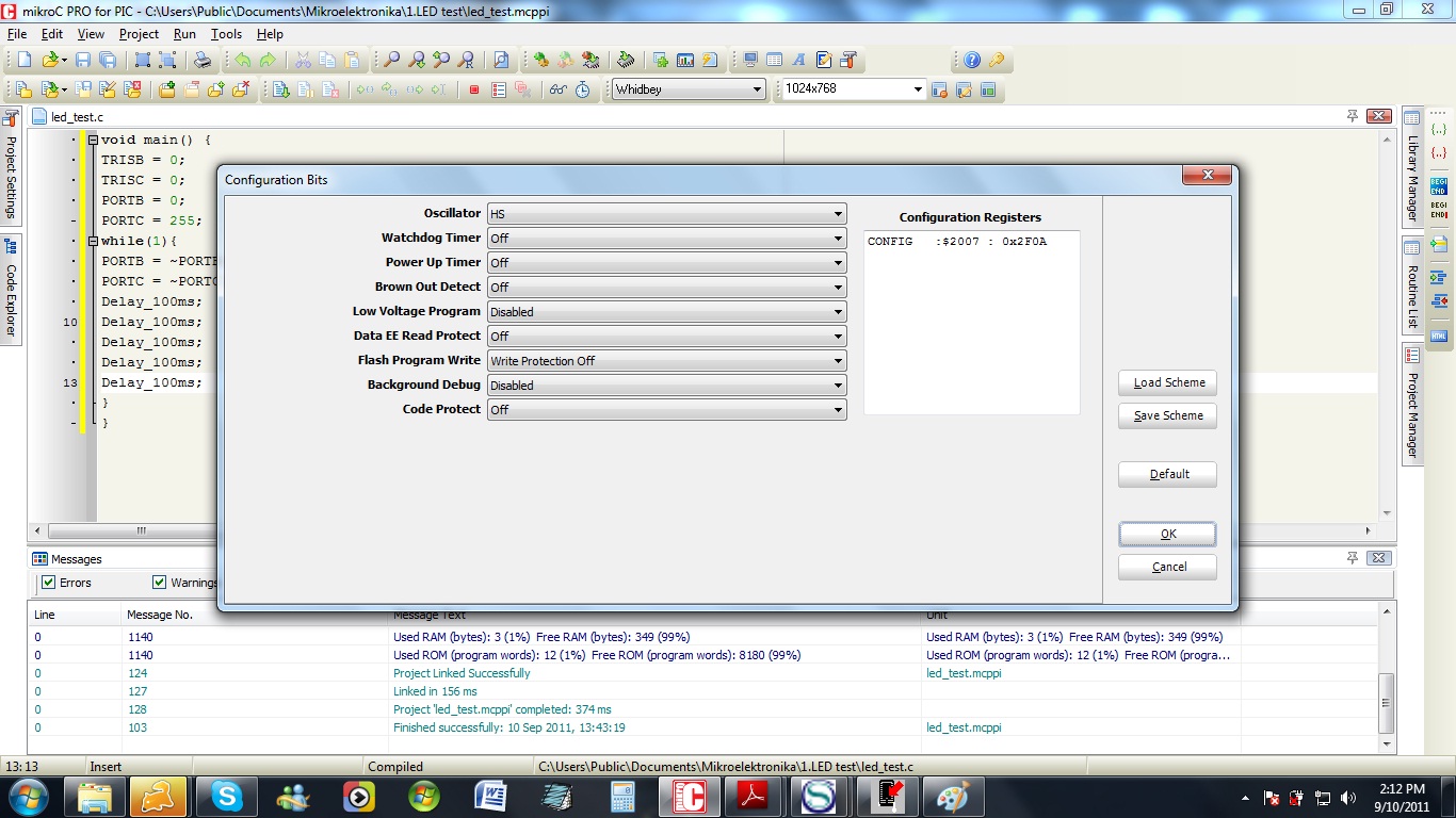
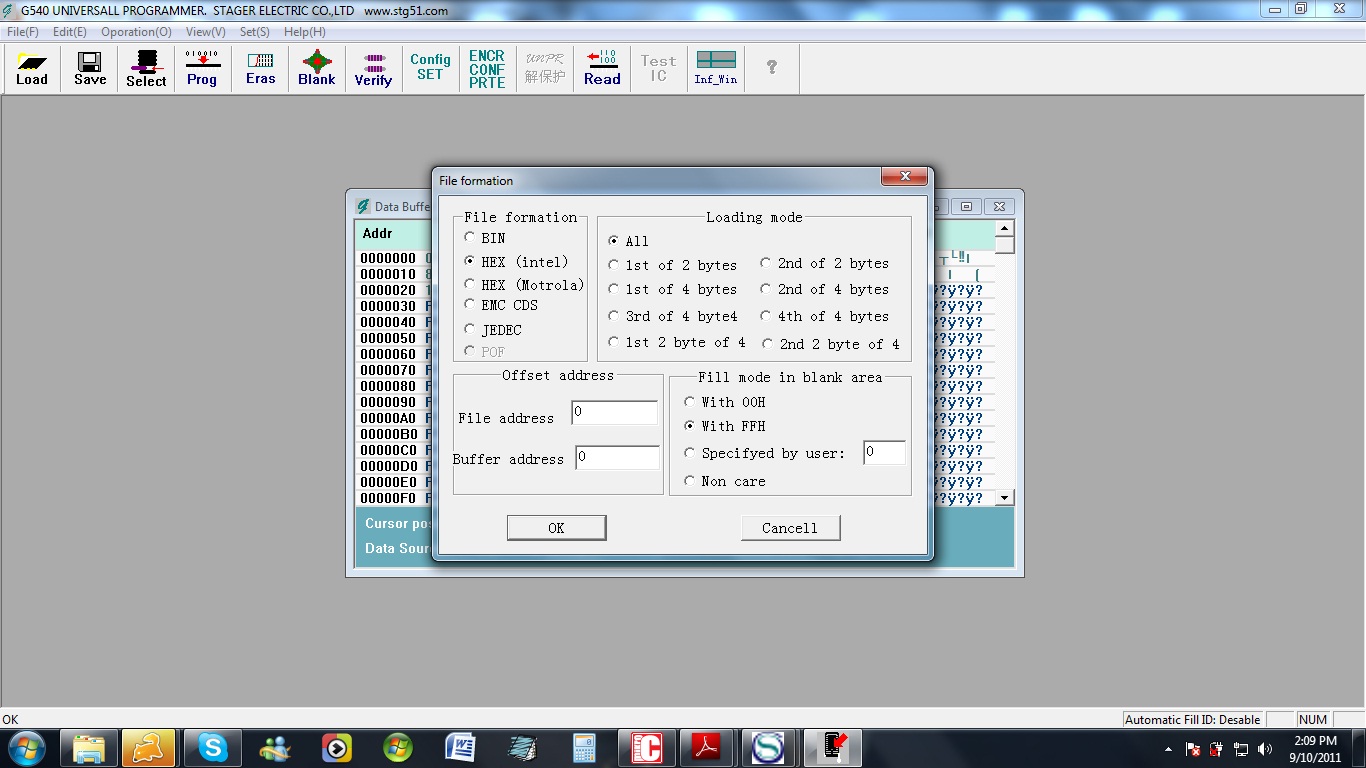
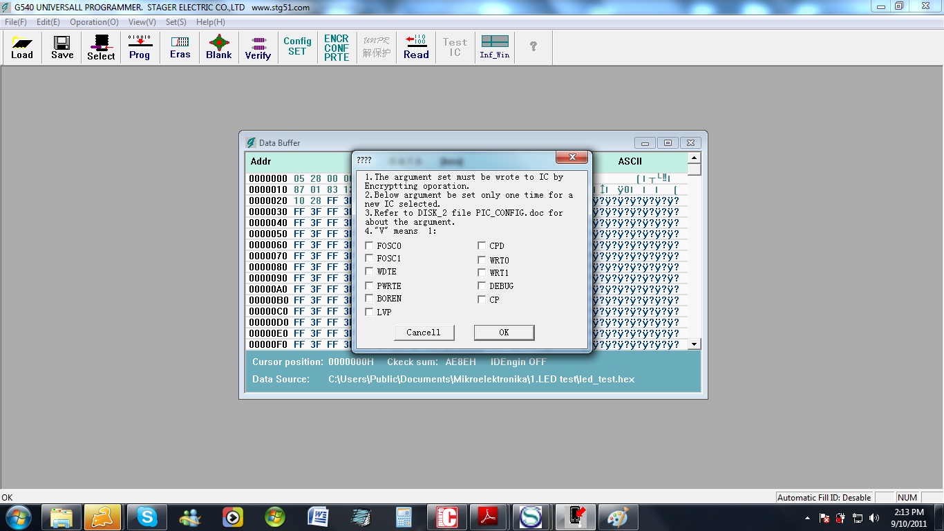
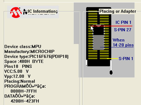
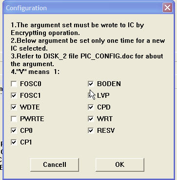
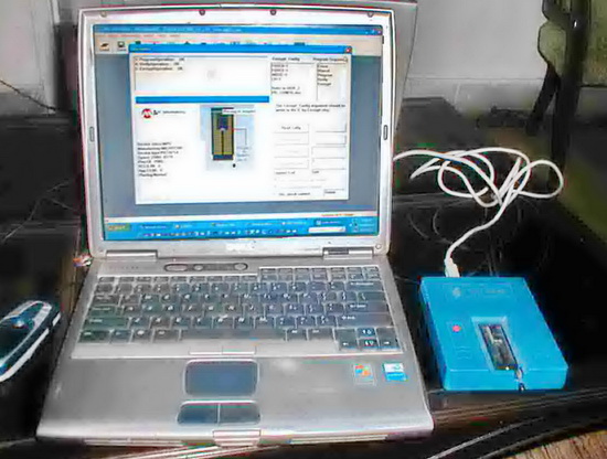
I have started learning PIC so i have written simple program in MickroC 2009 in C for led on/off. The program is simulating fine in "PIC simulator IDE" but when i try to burn it through my G540 programmer it gives the error shown in fig4. May be i have no idea of config bits and there matching is must i think????

Additional: I am using 12 MHZ crystal with 27pF capacitors. But burning is the first issue :(

void main() {
TRISB = 0;
TRISC = 0;
PORTB = 0;
PORTC = 255;
while(1){
PORTB = ~PORTB;
PORTC = ~PORTC;
Delay_100ms;
Delay_100ms;
Delay_100ms;
Delay_100ms;
Delay_100ms;
}
}


I have no idea of the programmer you use, but I think that you need to set the config bits in the programmer software which (maybe) can not read the config bits from the HEX file. This happened with my TOP2005 programmer before. Download the PIC16F876A datasheet and go to the configuration bit settings (page 146).

FOSC0 = 0
FOSC1 = 1
WDTE = 0
PWRTE = 1
BOREN = 0
LVP = 0
CPD = 1
WRT0 = 0
WRT1 = 0
DEBUG = 0
CP = 1

Set these in the configuration menu.

Hope this helps.
Tahmid.
 
Thanks for the reply Tahmid. So should i set these values in the mikroC also or just in the programer software?

Well i set it in both but programer still gives error of "NO word configuration in HEX file". Anyways i forced the program to burn and it worked :)

What programer are you using and what compiler are you using MPLAB or MikroC? Since I am beginning so its better to have an experienced suggestion.

Anyways thanks again and do me a favor, link me a tutorial (easy1 and step by step) or a good eBook if you have it.

highway_blues@live.com


According to datasheet,most suitable for this burner in start is setting for the reading content allowed (code protection disabled)
If you enable code protection, when you read back,youu will see only zeros. you think it is not programed wright.
Actually programe is there and if ok then it will run.
If you ser code protection disabled ,you will see the actual code in memory. and you confirm programmer is ok.

FOSC0 = 1 hc osc
FOSC1 = 0 hc osc Above 4MHz HC setting is used

WDTE = 0 disabled Watchdog timer if not took care off in software, will continually resets the microcntroller .

PWRTE = 0 disabled Initial delay timer for oscillator to get stabilized.

BOREN = 0 disabled Brownout, when power supply drops below certain level, it resets the microcntroller.

LVP = 1 disabled Low voltage programming disabled, as two i/o used and programmer can do otherwise
CPD = 1 disabled protection disabled so data in eprom can read back

WRT0 = 1 disabled Write protection off
WRT1 = 1 disabled

DEBUG = 1 disabled Debuger disabled

CP = 1 disabled Programme data can be read back

So cofig word is,

B'1111100111010'
You may try other settings but oscillator settings are important.
When both bits are cleared, it is set for LP. 32KHz to 200KHz
range.
Now about programmer,
Every time you load a hex file. a pop up dialogue say ' None configuration word in hex file. Please set it after loading'
It is chinese english. Actually you have already loaded the hex file. It also means after this session when next time you are gonna programe, dont forget to set the config bits. But dont worry next time this pop up will be there. But then when you observe config bits, your previous settings will be there. So you will soon start ignoring this message. Its funny after setting the bits, you think it is necessary to reload the hex file. When you do so ,message reappears and now you are confused. After setting the bits you only have to click Prog. and next time you burn hex, just forget it, click ok and then click Prog. The old settings will be there for that chip.
 

Attachments

  • 16f876A onfiguration.pdf
    42.6 KB · Views: 95
Last edited:
:evil: I hate china products. Thanks for letting me know. It wasted lots of my time. I'll be ignoring this message from now on.
 

I often use PIC16F676. It is shown as 18 pin dip in zif socket position diagramme. But one thing i have to say, It neither burns itself nor the microcontroller when mounted wrongly. It burns flawlessly.

67_1315690827.jpg

This is default settings for PIC16F876A

31_1315690569.jpg

82_1316088905.jpg
 
Last edited:

I used the PICKIT2. Recently it got damaged, so I made a PICKIT2 clone for myself. Much better than the TOP2005 programmer I used before. Set them in mikroC as well, but if the programmer software doesn't recognize it, it doesn't really matter. I use mikroC and I really like it.

This is a really good and free book: PIC Microcontrollers - Programming in C - Free Online Book - mikroElektronika

Hope this helps.
Tahmid.
 

Hi guys. Another problem :(

Port B is blinking but RB6 and RB7 are not working. LVP and debug mode is off. I have read on a form

RB6 and RB7 output not working

That its good to define config bit in your source code so it will over ride the programmer settings. Unfortunately i never found the regarding example in Mikroc.

Well if there is something else wrong, plz let me know.
 

In mikroC, you don't set the config bits in the code. Setting them as you have done using Project > Edit Project essentially does the same thing. However, your programmer seems not to recognize it. Didn't you set debug and power up timer off in the config settings?
 

Debug is set off and power up timer was on in both software and hardware---->NO good.
After that i set off the power up timer (debug off)in both software and hardware---->no good

---------- Post added at 23:07 ---------- Previous post was at 23:06 ----------

Same problem in ISIS simulation.

---------- Post added at 23:10 ---------- Previous post was at 23:07 ----------

Some people just say that dont use these pins as they are for programing purpose...i think they should serve both purposes. I also used pull up and pull down resistor of 10k but no good.

---------- Post added at 23:24 ---------- Previous post was at 23:10 ----------

look at here

**broken link removed**

its says that these pins are for programing purposes.

Any ways i am thinking if the Register "option_reg" has to do something with it.

---------- Post added at 23:36 ---------- Previous post was at 23:24 ----------

Got it working...my mistake. I was thinking Debug mode off at "0" but it is off at "1".

I need to take some time off:-|
 

hi sajid khan how are you please must be set configuration of your editor if you want to run file in isis you must be set xtl 20,000mhz this is only hint not sure because i am use flowcode programming software his file if i want to run in isis must be set as 20.000mhz try make some positive relate
 

Attachments

  • pic2.JPG
    pic2.JPG
    232.6 KB · Views: 183
  • pic1.JPG
    pic1.JPG
    219.9 KB · Views: 101
Last edited:

Are you compiling your code in a Release or Debug release?

Both RB6 and RB7 are used exclusively in a Debug release for clock and data, possibly regardless of the programs initialization of these pins.

BigDog
 
Last edited:

Hey Tahmid: Need to ask some questions about AD conversion.

I have seen ADCON0 and ADCON1 registers in the data sheet.

1. I have to use more than 1 adc channel so should i change entire value of ADCON0 register while channel selection or can i assess its individual bits i.e. CHS2:CHS1? any example?

2.I don't understand the difference between GO/DONE and ADON bits in ADCON0 register as it seems both have the same function?

3. didn't get the meaning of ADFM bit in ADCON1 register?

4.About vref of ADC, should it be in analog mode if vref is to be set internally? of course it is to be set analog if vref(-) and vref(+) is to be provided externally. when we say vref is to be set internally, it means vref(-)=0 and vref(+)=5, no other voltages can be set internally,right?

---------- Post added at 07:01 ---------- Previous post was at 06:58 ----------

Are you compiling your code in a Release or Debug release?

Both RB6 and RB7 are used exclusively in a Debug release for clock and data, possibly regardless of the programs initialization of these pins.

BigDog

hey bigdog
I am compiling my code in MikroC and debug mode is off. its working on the bread board but not in ISIS.
 

I am compiling my code in MikroC and debug mode is off. its working on the bread board but not in ISIS.

I just find it strange you are only having problems with RB6 and RB7 and they happen to be the pins required for Debug.

Can you upload your Proteus design and a current version of your source code? I'd like to take a look at it and see what I can find.

BigDog
 

I just find it strange you are only having problems with RB6 and RB7 and they happen to be the pins required for Debug.

Can you upload your Proteus design and a current version of your source code? I'd like to take a look at it and see what I can find.

BigDog

There is also a setting in ISIS for crystal and config bits, may be i don't know the right value for it.
And can you answer me about my ADC questions.thanks.
 

Attachments

  • led_blinking.rar
    13.5 KB · Views: 74

BigDog, never trust simulators :smile:, as Sajjadkhan wrote: I am compiling my code in MikroC and debug mode is off. its working on the bread board but not in ISIS.

It's not that I trust Proteus, to the contrary I have found numerous bugs in the Proteus simulator and have documented them and at times found work arounds or fixes.

I would like to examine this issue closer and in the future if an individual has a similar problem without access to hardware I can more effectively troubleshoot the issue.

Besides, I'm willing to spend my time with this issue not someone elses.

BigDog

---------- Post added at 03:26 ---------- Previous post was at 03:22 ----------

Thanks Sajjadkhan.

I let you know what I find out concerning this issue. By the way, I just found a workaround for the MikroC EEPROM library and its incompatibility with Proteus examining an issue like yours.

I'm working on a response to your ADC questions now.

BigDog

---------- Post added at 03:43 ---------- Previous post was at 03:26 ----------

1. I have to use more than 1 adc channel so should i change entire value of ADCON0 register while channel selection or can i assess its individual bits i.e. CHS2:CHS1? any example?

You can effectively use both methods:

Set the entire register:
ADCON1 = 0x00;

Or configure just a select number of bits, such as PCFG3:pCFG0.

Sets PCFG3:pCFG0 to configure all pins as digital I/O except for AN0, while leaving the rest of the bits unchanged.
ADCON1 |= 0x0E;

Or turn off/reconfigure select bits, such as PCFG3:pCFG0.

Sets PCFG3:pCFG0 to configure all pins as ADC AN0-AN7 while leaving the rest of the bits unchanged.
ADCON1 &= 0xF0;

2.I don't understand the difference between GO/DONE and ADON bits in ADCON0 register as it seems both have the same function?

Setting ADON =1; powers up the ADC module. Setting GO/DONE=1; begins the conversion process and remains set until cleared by hardware to signify the process has completed. Therefore after setting GO/DONE you can monitor it, once it has been cleared the conversion process has completed and the value is available in the ADRESH:ADRESL register pair.


BigDog

---------- Post added at 04:16 ---------- Previous post was at 03:43 ----------

3. didn't get the meaning of ADFM bit in ADCON1 register?

The resulting value of the ADC conversion using a PIC16F877A is a 10-bit value, while the ADRESH:ADRESL register pair is a combined 16-bit. The ADFM bit controls the placement of the value in relation to these 16-bits of the register pair by left or right justification.

If ADFM = 1;, then the ADC value is right justified by filling the LSB bit of the value into the LSB of the ADRESL with the remain bits of the value filling the rest of the ADRESL and the remaining two MSBs are placed in the two LSBs of the ADRESH register.

If ADFM = 0;, then the ADC value is left justified by filling the MSB bit of the value into the MSB of the ADRESH with the remain bits of the value filling the rest of the ADRESH and the remaining two LSBs are placed in the two MSBs of the ADRESL register.

Any unused bits in either format are padded with zeros, in other words cleared.

The left justified format, ADFM = 0;, is used quite often when only an 8-bit value is desire, the required 8-bits are contained entirely in the ADRESH register and the two remain LSBs contained in the ADRESL register can be ignored.

4.About vref of ADC, should it be in analog mode if vref is to be set internally? of course it is to be set analog if vref(-) and vref(+) is to be provided externally. when we say vref is to be set internally, it means vref(-)=0 and vref(+)=5, no other voltages can be set internally,right?

Correct, if using internal VREF, you should set the VREF+/VREF- pins to either ADC or Digital I/O by configuring the ADCON1 register.

If you configure for internal VREF, the VREF+ is set to Vdd and the VREF- is set to Vss respectfully.

However, there are modes where an external VREF+ can be furnished while VREF- is still set to Vss, by proper configuration of the PCFG3:pCFG0 bits.

Reference PIC16F87XA Data Sheet, pg 127, Section 11.0 ANALOG-TO-DIGITAL CONVERTER (A/D) MODULE

Reference Microchip Midrange Family, Section 23. 10-bit A/D Converter

Hope the info helps. Let me know if you have any additional questions.

BigDog
 
Hey Tahmid: Need to ask some questions about AD conversion.

I have seen ADCON0 and ADCON1 registers in the data sheet.

1. I have to use more than 1 adc channel so should i change entire value of ADCON0 register while channel selection or can i assess its individual bits i.e. CHS2:CHS1? any example?

2.I don't understand the difference between GO/DONE and ADON bits in ADCON0 register as it seems both have the same function?

3. didn't get the meaning of ADFM bit in ADCON1 register?

4.About vref of ADC, should it be in analog mode if vref is to be set internally? of course it is to be set analog if vref(-) and vref(+) is to be provided externally. when we say vref is to be set internally, it means vref(-)=0 and vref(+)=5, no other voltages can be set internally,right?

---------- Post added at 07:01 ---------- Previous post was at 06:58 ----------


hey bigdog
I am compiling my code in MikroC and debug mode is off. its working on the bread board but not in ISIS.

1) You can change the entire register if you want, but changing the individual bits will do.
2) ADON determines whether the ADC module is on or off. Setting GO/DONE starts an ADC conversion, it is then cleared by hardware after conversion is started. To start the conversion by setting GO/DONE, ADC needs to be on with ADON = 1
3) ADFM determines whether the result is left-justified or right-justified. When ADFM = 1, the result is right-justified. The 2 MSBs are stored in ADRESH, the 8 LSBs are stored in ADRESL. By reading ADRESH and ADRESL you get a 10-bit result. When ADFM = 0, the result is left-justified. The 8 MSBs are stored in ADRESH, 2 MSBs are stored in ADRESL. By reading ADRESH and the 2 MSBs of ADRESL, you get a 10-bit result. By reading ADRESH only, you only get a 8-bit result.
4) If VREF is set internally to VDD and VSS, then the pins are free. If you use them for ADC inputs, configure them for analogue, if you use them as digital pins, configure them as digital.

Hope this helps.
Tahmid.
 

OK so now i have understood and thanks. Proceeding further about programing these:

1. So ADON should be 1 only when i am using ADC. I mean even if i am not using ADC, keeping it 1 doesn't matter right, i just have to set GO/DONE to start conversion when ever i needed?

2.Should i clear ADON before selecting a channel, would there be any effect if i don't?

3.There can be unknown state in between when ADC switches form one channel to another. Is there any possibility that the Wrong value of ADC is stored in some register (in which i am trying to save it) ?

4. Is there any register greater than 10bit in this PIC where i can perform 10bit addition and like wise? If not then suppose i perform add on lower 8bits and it overflows , suppose i add 255 + 40 then there should be 1 in upper register and and 39 in the lower register....how would i achieve that?

---------- Post added at 21:46 ---------- Previous post was at 21:01 ----------

One more thing in this post https://www.edaboard.com/threads/220574/, Thamid has used ANSEL register to make pins analog but in my PIC datasheet there is no ANSEL register. The port is directly connected to ADC, i just have to turn ADON =1 to use ADC right?

---------- Post added at 21:56 ---------- Previous post was at 21:46 ----------

In keil When i use to program 8051 i can see the values in A and B register R0-R7..How can i do it here in MikroC?
 

Status
Not open for further replies.

Similar threads

Part and Inventory Search

Welcome to EDABoard.com

Sponsor

Back
Top