Continue to Site

Welcome to EDAboard.com

Welcome to our site! EDAboard.com is an international Electronics Discussion Forum focused on EDA software, circuits, schematics, books, theory, papers, asic, pld, 8051, DSP, Network, RF, Analog Design, PCB, Service Manuals... and a whole lot more! To participate you need to register. Registration is free. Click here to register now.

Problem with a integrator in LTspice

Status
Not open for further replies.

icaroM98

Newbie
Joined
Oct 14, 2021
Messages
3
Helped
0
Reputation
0
Reaction score
2
Trophy points
3
Activity points
22
Hello,

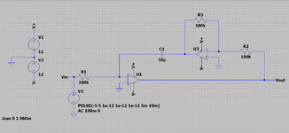
I'm trying to simulate an integrator circuit in LTspice, but it doesn't work.
By the transfer function, the circuit behaves like an integrator and like a low-pass circuit.

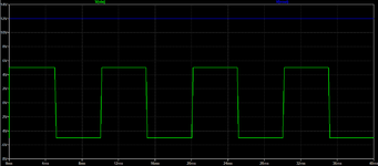
When I input a square wave, the desired input signal should be a triangle wave, but the output that the LTspice shows is a constant saturated 12V signal.

What could be wrong with this simulation? I have attached the simulation images.

Thank you very much in advance.
 

Attachments

  • opamp_integrator.png
    opamp_integrator.png
    19.8 KB · Views: 162
  • opamp_integrator_output.png
    opamp_integrator_output.png
    13.6 KB · Views: 181

By using an additional inverter function, your circuit has positive instead of negative feedback. To make an integrator, you can omit U2 and connect C1 to U1 output.

Initial condition of the integrator however needs special attention. It can be achieved by an explicite .IC statement, using the UIC option in transient simulation or a reset circuit.

1634226235809.png
 
Last edited:
I don't understand why the circuit has positive feedback. Can you explain to me?

Also I tried using the 'uic' option in transient simulation.

As a reference, I have also attached my calculations for the expression of the circuit's output. Sorry for the poor image quality.
 

Attachments

  • 20211014_124126.jpg
    20211014_124126.jpg
    314 KB · Views: 126
Feedback loop is constituted by two inverting amplifier stages, results in overall positive feedback. Unstable by design.
--- Updated ---

If you want a non-inverting integrator, search for deboo integrator circuit.
 
Last edited:
That Cool! It didn't cross my mind that this circuit was unstable. This other circuit you indicated helps me a lot.
 
The opamp has no DC negative feedback (a resistor parallel with the integrator capacitor) causing its DC gain to be almost 1 million. Then its output will probably be at the positive or negative supply caused by it amplifying its DC input offset voltage 1 million times.
 
Status
Not open for further replies.

Part and Inventory Search

Welcome to EDABoard.com

Sponsor

Back
Top