Continue to Site

Welcome to EDAboard.com

Welcome to our site! EDAboard.com is an international Electronics Discussion Forum focused on EDA software, circuits, schematics, books, theory, papers, asic, pld, 8051, DSP, Network, RF, Analog Design, PCB, Service Manuals... and a whole lot more! To participate you need to register. Registration is free. Click here to register now.

Problem with 555 toggle circuit

Status
Not open for further replies.

Pankajghawte

Newbie level 6
Newbie level 6
Joined
Oct 14, 2013
Messages
13
Helped
0
Reputation
0
Reaction score
0
Trophy points
1
Location
India
Visit site
Activity points
109
I'm using attached circuit to switch 5V relay. httpimg441_imageshack_usimg4414555pushbuttoncircuit.jpg instead of using resi.1K and transistor 2N 3904 I'm using resi. 100 ohm and transistor 2N2222. But the issue with the circuit is that when I press button relay gets ON and stays high even after releasing button and gets OFF when I again press the button but if I press and hold button (accidently) more than 1sec (I guess) the relay gets ON initially and gets OFF immediately. Please advise correct action.:|
Regards,
Pankaj
 

You need a diode across your relay coil , else you are going to blow something when the relay turns off.
100 ohm base drive is too small , go back to 1K.
Just a start.
 

The real question is :- what do you want it to do? The circuit is unusual but is working but its not doing what you want it to do.
Frank

I've connected DTMF decoder 8870 which turn on 5v relay first. Then that relay is used to switch the button which was shown on pervious 555 toggle circuit. And finally 555 output is used to switch another 5v Relay to operate water pump motor. My basic intention of this circuit is to ON & OFF the water pump through Cell phone using only 1 keypad key. I do not have any issue with 8870 circuit but the 555 toggle circuit is giving an issue.

Pankaj

- - - Updated - - -

Yes, I've connected protection diode across relays already. I'll try 1K and will let you know the results.

- - - Updated - - -

The real question is :- what do you want it to do? The circuit is unusual but is working but its not doing what you want it to do.
Frank

I've connected DTMF decoder 8870 which turn on 5v relay first. Then that relay is used to switch the button which was shown on pervious 555 toggle circuit. And finally 555 output is used to switch another 5v Relay to operate water pump motor. My basic intention of this circuit is to ON & OFF the water pump through Cell phone using only 1 keypad key. I do not have any issue with 8870 circuit but the 555 toggle circuit is giving an issue.

Pankaj
 

Sounds to me like you want a circuit to toggle every time the button / relay is pushed.
A D-type flip-flop in a toggle config sounds like a better option?
 

Yes, I've connected protection diode across relays already. I'll try 1K and will let you know the results.

- - - Updated - - -

My circuit is almost ready and working well but only the problem is if I press and hold button (accidently) more than 1sec (I guess) the relay gets ON initially and gets OFF immediately. 555 pin -3 gives 3.56 volt when the button is pressed (with 100 ohm & 2N2222). The pin-3 voltage drop from 4.68 to 3.56 when the button is pressed. This is something creating problem because 2N2222 B-E sat. voltage is 1.3v which affects 555 pin3 voltage. What do you think?
 

Quick search found this.
**broken link removed**
Could be what you need. Easy to mod for your application.
Maybe add a RC circuit on the switch/relay input to clear up any relay bounce causing the circuit
to toggle multiple times.
Neddie

- - - Updated - - -

Last post didn't come through. 100 ohms is too small, you are going to damage the transistor.
Use 1K ohm. I've simmed your circuit , should work fine if wired correctly.
Neddie
 

If you have already built your circuit , stick with it .
It should work assuming the values and wiring is correct.
 

ok Thanks a lot. I'll connect 1K behind 2N2222 and will let you know the results.
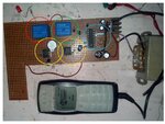
ckt.jpg
Hello Guys,
Here is my ckt explanation,
- Yellow circle area has an astable 555 ckt with small 2 sec buzzer. This is fitted which will be activated once the pump activated & user can hear buzzer sound & confirms that the pump is started running.
- Blue circle has DTMF 8870 which is decoding the cell phone keypad signal to actuate relay (shown in the green circle) through 2N2222. Please note that, I’d like to use only one output channel from DTMF decoder.
- Orange circle area has a 555 ckt which I’d communicated earlier. The switching output is controlled by Green circle relay & the 555 (Orange circle) output is given to the 2N2222 to control Red circle relay. The Red circle relay actually switches the pump.
- An issue still persists. If I hold the cell phone button more than 1 sec. the Green relay start heavily chattering or bouncing.

I’ve also tried monostable 555 ckt with 1sec o/p high timer in between Green relay & DTMF output to trigger Green relay for particular time period only but that also didn’t help.
Could this chattering be an issue? Any suggestion to avoid this chattering or boucing??
 

View attachment 103023
Hello Guys,
Here is my ckt explanation,
- Yellow circle area has an astable 555 ckt with small 2 sec buzzer. This is fitted which will be activated once the pump activated & user can hear buzzer sound & confirms that the pump is started running.
- Blue circle has DTMF 8870 which is decoding the cell phone keypad signal to actuate relay (shown in the green circle) through 2N2222. Please note that, I’d like to use only one output channel from DTMF decoder.
- Orange circle area has a 555 ckt which I’d communicated earlier. The switching output is controlled by Green circle relay & the 555 (Orange circle) output is given to the 2N2222 to control Red circle relay. The Red circle relay actually switches the pump.
- An issue still persists. If I hold the cell phone button more than 1 sec. the Green relay start heavily chattering or bouncing.

I’ve also tried monostable 555 ckt with 1sec o/p high timer in between Green relay & DTMF output to trigger Green relay for particular time period only but that also didn’t help.
Could this chattering be an issue? Any suggestion to avoid this chattering or boucing??


Guys I need advise. Please help
 

Can you not give us a full circuit diagram.

- - - Updated - - -

If the "Green" relay is chattering , it's probably something to do with the DTMF decoder , as this drives the green relay. (I think :0) )
If the output from the DTMF decoder is chattering , for reasons unknown , try driving the 2n2222 via a diode , resistor , capacitor combination. With the correct values you can "filter" out the drive that is causing the chattering. The downside is that you won't be able to retrigger the relay for the filter time.

Hope this makes sense.
Neddie
Thanks for you support guys. Now I've removed the Green relay and I'm using 2N3904 with 10K base transistor directly to flip-flop the 555 output. The chattering problem is gone. But there is only one issue that on the quick power ON/OFF cycle 555 output gets ON & OFF (this is unpredictable). Then I measured the positive rail supply (5 VDC) which taken from 6V transformer & IC 7805, I've noticed there was voltage spike of 10-18 V during sudden power OFF which affects the 555 output. How can I get rid off this?

Pankaj
 

Are there any relays in the circuit that don't have diodes across them.
I don't quite understand your explanation. Are you saying that the 555 sometimes triggers when you apply power.
This could be fixed by putting a reset circuit (cap to gnd , resistor to supply) on your 555 reset pin.

" I've noticed there was voltage spike of 10-18 V during sudden power OFF which affects the 555 output"

I don't understand how you can be affecting the 555 "OUTPUT" if ,you have removed power?
A 10-18V spice could be caused by some "un-snubbed" inductance , hence my first question.
By "POWER OFF" do you mean removing power from the circuit , of turning off the relay. If it's turning off the relay , see first
question :0)

Yes you are right. By Powering Off the from the circuit, the 555 operated relay gets ON for few micro second. The protection diode is soldered across Relay and 555 Pin 5 grounded with cap 0.01 MF & pin 4 is also grounded with R (10K)-C (0.1 MF) combination to ensure always OFF state of 555 Output. It is also true that there is quick surge in the voltage around 10-18V when I power OFF the system. I think this is the issue. I read about Subber circuit on the internet but still I'm not able to figure out resistor and Capacitor value for subber circuit.

Pankaj
 

Status
Not open for further replies.

Similar threads

Part and Inventory Search

Welcome to EDABoard.com

Sponsor

Back
Top