Continue to Site

Welcome to EDAboard.com

Welcome to our site! EDAboard.com is an international Electronics Discussion Forum focused on EDA software, circuits, schematics, books, theory, papers, asic, pld, 8051, DSP, Network, RF, Analog Design, PCB, Service Manuals... and a whole lot more! To participate you need to register. Registration is free. Click here to register now.

problem using Step down transformer as step up

Status
Not open for further replies.

sagar474

Full Member level 5
Full Member level 5
Joined
Oct 18, 2009
Messages
285
Helped
5
Reputation
10
Reaction score
5
Trophy points
1,318
Location
India,kakinada
Visit site
Activity points
3,123
I'm working on a inverter project.
I like to use a step down transformer as step up 12 volts ac to 230 volts dc
I flipped primary and secondary of the 12 0 12 transformer. but getting out put only around 20 volts.
 

I once tried to do the same thing. I too was disappointed at the low output.

Why can't the windings transfer the same wattage in either direction? After years of wondering, I think I figured it out.

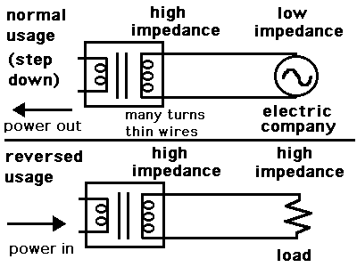
This diagram shows what we're trying to do.

The electric company is very low impedance. The high voltage side is designed to present a high impedance to the electric company.

We want to substitute a load instead. But our load is high impedance. Therefore we cannot expect to get the same transfer of power.

9733280300_1407669176.gif
 

Measure the unloaded voltage of your "12V" transformer and it is probably 14V. They make it produce 14V because its windings have resistance that reduces its voltage to 12V when it has its rated load.

Now reverse it and apply 12V RMS to its "12V" winding that is actually 14V. Then the unloaded high voltage is (12V/14V)/230V= 197V and is less (maybe 169V) when loaded.

Maybe instead of a sinewave with peak voltages of 230V x 1.4124= 325V your inverter produces a squarewave with peaks at 169V. Then your meter measures 169V/1.414= 120V. But the peaks are probably less because the output transistors or Mosfets have some voltage loss.

I think your circuit or your transformer is defective for it to produce an output of only 20V. Post the schematic of the inverter (is it the defective circuit from Aaron Cake's site?).

My transformers are high quality and produce 12.5V when unloaded so I can use a 10V transformer that produces 10.5V when unloaded in an inverter and get almost the output voltage I need.
 

It should work.
They Do work on My Inverter Circuit.

I Think you have a Circuit Problem.
Lets See your Inverter Schematic?

However Proper Inverter Transformers will have the 12-0-12 Primary wound First on the Core with the 230 Volt winding over top it it.
ALSO for BEST Efficiency the 12-0-12 Should be Bifilar Wound.
 

Hi,

Measure the unloaded voltage of your "12V" transformer and it is probably 14V. They make it produce 14V because its windings have resistance that reduces its voltage to 12V when it has its rated load.

Now reverse it and apply 12V RMS to its "12V" winding that is actually 14V. Then the unloaded high voltage is (12V/14V)/230V= 197V and is less (maybe 169V) when loaded.

absolutely right.

And in addition: If now you want to put more than 14V on the transformer input to get 230V AC output, then the core may become saturated. Increasing current, decreasing efficiency. ;-(

*********
But you say 230V DC. This should be possible. you need a bridge type rectifier and a capacitor at the output. setup your voltmeter for DC.

Klaus
 

An inverter produces AC at its output to replace mains electricity when you are away from civilization.
Thomas Edison used DC for mains electricity 132 years ago.
 

Impedance ratio is the ratio of Voltage stepup and Current Stepdown so it is transforms by N squared ratio. Also a well regulated transformer has a very low transfer impedance for low loss and low load regulation tolerance. This means the IR drop from conduction losses is low. How low? ... depends on class of transformer.. best in class ~2%, typical 4~8%,

( Side note... but in MW & GW size transformers, lower transfer impedance increases cost but increases efficiency but also increases damage from short circuit current gain over rated current, where Zt= Irate / I short cct. thus Zt specifications increases with power capacity from 4% to 10% in huge AC power transformers).

Now using a bridge diode and capacitor as "No load" you will get the peak voltage or 1.414 x RMS voltage. But the Capacitor has very low ESR as well as the diode bridge has very low ESR so startup up is a high current load.

Any DC load is transformed by N squared to the source. If N is the voltage ratio from 12-0 to 230 is almost N=20 from 12-0-12 (24) it is almost N=10

Using an example of 12V to 230V if you apply a load of 400 Ohms with a N=20, the load on the 12V side appears as 1 Ohm.
 

"No load" you will get the peak voltage or 1.414 x RMS voltage.

This Applies to a SINE WAVE.
Not for a Square wave output Inverter.
 

Your inverter is running at less then 200HZ?, if not the leakage inductance and iron losses will ruin the transformer action. Within the working frequency and maximum power level, transformers do what is written on them, i.e. a voltage transformation ratio of 230 :12. They do have a power loss and even in the smallest transformers is never over 15 %, and in larger ones is 5%.
I suspect that your inverter design is faulty.
Frank

ust a suggestion

i think it should work with your invert-er, however there are a few things
you need to do.

1/use 50-60hz if its a mains transformer
2/ tune the output of the transformer with a capacitor
3/ the voltage spec of the transformer is RMS for pk= RMS/0.707
= you supply rail-voltaged drops, for the same output RMS
4/ consider using a sine wave generator and amplifier instead
may be a linear one or class D amp.
5/ square wave type invert-er voltage boosters are ok for some type of equipment but they can cause you equipment to make funny noise. True sine wave is better.
 

Status
Not open for further replies.

Part and Inventory Search

Welcome to EDABoard.com

Sponsor

Back
Top